Laser Cutting Hackerspace MakerCoin
If you have followed any of the tutorials on performing the CAD work on the Hackerspace MakerCoin (Fusion 360, OnShape, CamBam), then this step will take you from the CAD design to making a physical object on the Hackerspace Laser Cutter.
Follow the below instructions to export the CAD design from your CAD software for use with the Laser Cutter Software
Export Instructions
Fusion 360
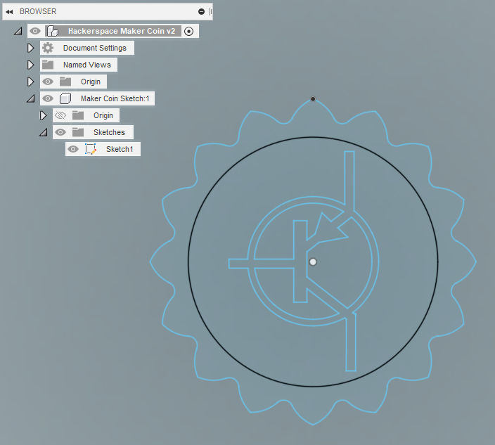
In the browser menu, find the sketch that you want to export.
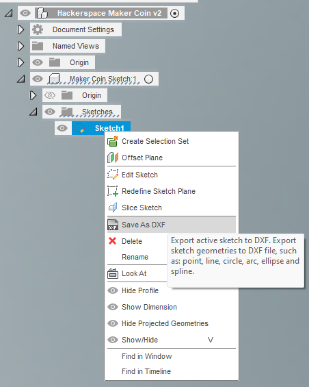
Right click the Sketch, and click “Save as DXF”
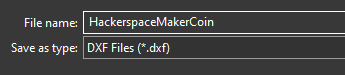
Select the location to save to, and give it a name.
Click save.
Onshape
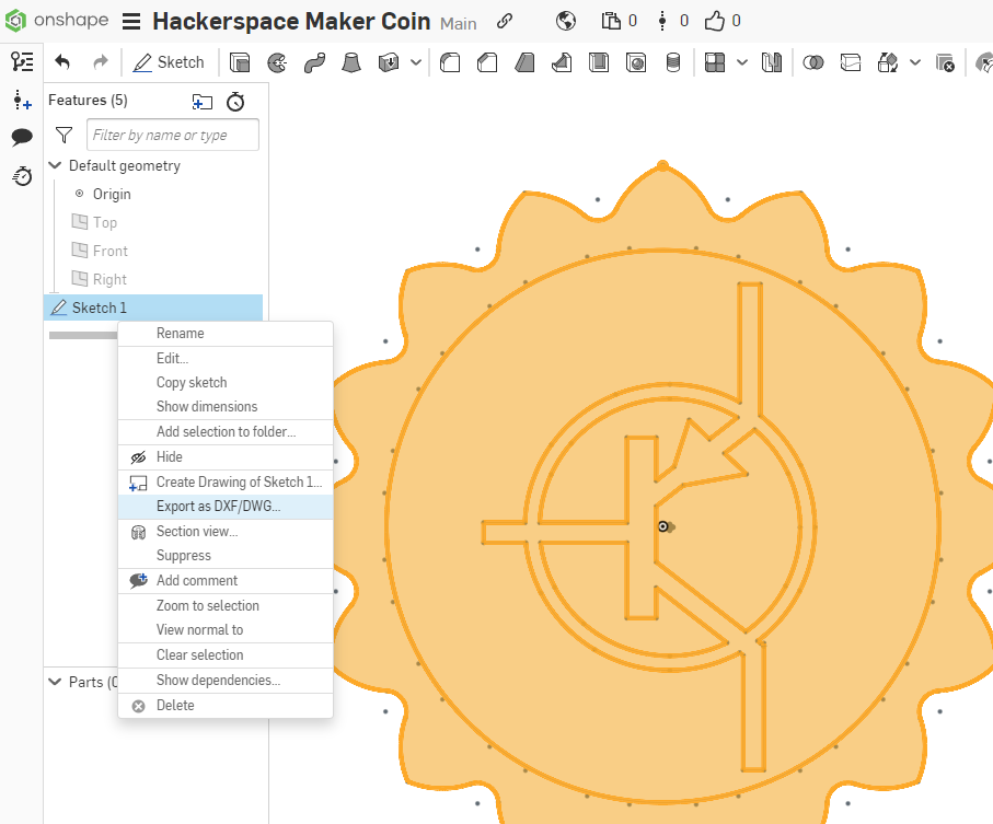
With the document open, select the Sketch in the left-hand window.
Right click the Sketch, and select “Export as DXF/DWG”
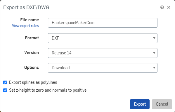
In the Export as DXF/DWG Dialog box, set the File Name to whatever you’d like. Here I’ve set mine to HackerspaceMakerCoin. Leave the rest of the options at their defaults.
Clicking Export will prompt your Browser to download the file.
CamBam Plus
With the job open, click File->Export->To DXF
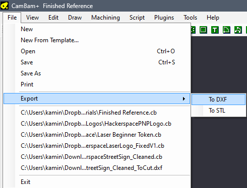
Select the location to save to, and give it a name.
Click save.
Laser Cutting Instructions
Getting Started
Open LightBurn
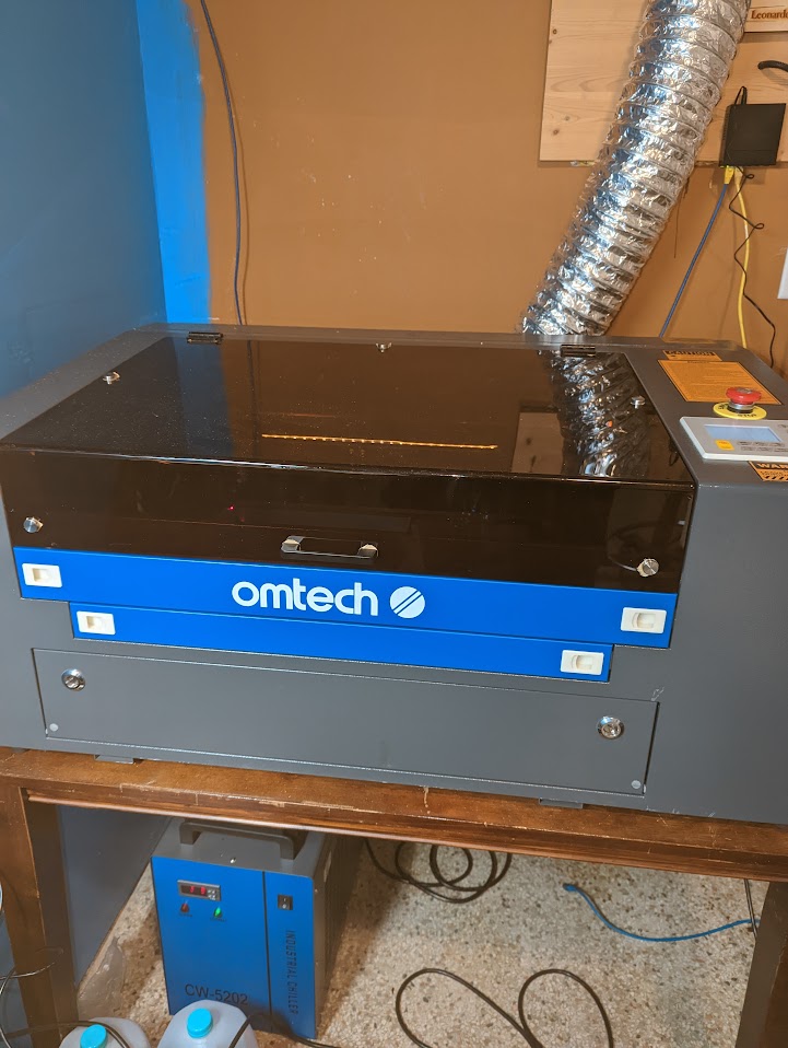
In the bottom left of the LightBurn Window, make sure the proper Laser Cutter is selected that you wish to use. This tutorial follows the instructions for the Omtech 12×20 50 watt laser.
Import your CAD DXF file by selecting File->Import
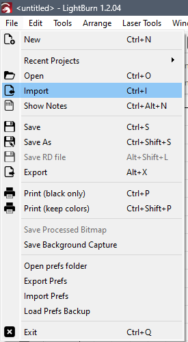
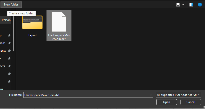
Select the DXF file from your computer
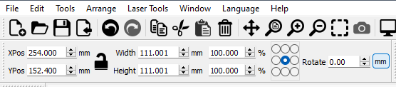
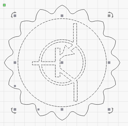
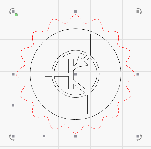
Near the top left of the LightBurn Window, you will be able to see the properties of the selected shape, including X and Y position on the workspace, the height and width, the manipulator positioning, rotation, and document units.
Given that we designed the file with millimeters in mind, make sure the units selection is in mm, and verify that the size of the exported shapes are in line with what you expected.
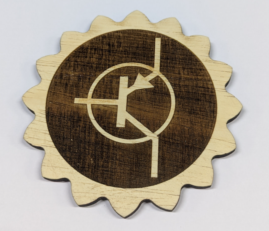
Here, the MakerCoin was designed to be 111mm in diameter.
Setting up the Laser Job
The Gainesville Hackerspace is working on a tested material library. A sample of that material library can be downloaded from <url> to facilitate you creating the LightBurn project from a non-Hackerspace computer.
With the Material Library downloaded, import it into LightBurn.
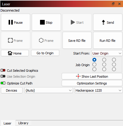
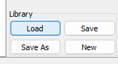
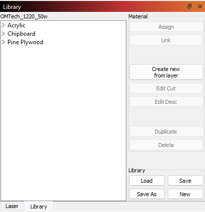
In the bottom right, in the panel with the Laser Controls tab, there is a Library Tab.
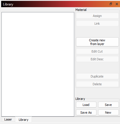
Click Load to start the import process
Select the downloaded Library file

Verify the Library has imported
Next we need to assign Layers to cutting parameters.
Typically, we assign Black to Raster Engraved geometry, Blue to Vector Engraved geometry, and Red to Vector Cutting Geometry.
Engraving passes typically only remove a portion of the surface material, while Cutting Passes are slower to cut all the way through the material.

Raster Engravings typically scan the laser beam back and forth over the surface of the material to create an image or empty space.
Think of it in the same way an inkjet printer might move.
Vector Engravings and Cutting tell the machine to follow the shape of the path that it is programmed to use.
Think of it like a pen plotter, or CNC Engraving Machine
While the colors are not important, the settings and order of operations are. Typically, you’d want to run a Raster Engraving pass first, then a Vector Engraving Pass, and finally the Vector Cutting pass.
For our MakerCoin, hold Control or Shift, and select the Circle, and the components of the PNP Logo, and assign it to the Raster Engraving Pass.
Simply select the Layer you wish to assign your selection to in the Layer Selection bar at the bottom of the LightBurn Window.

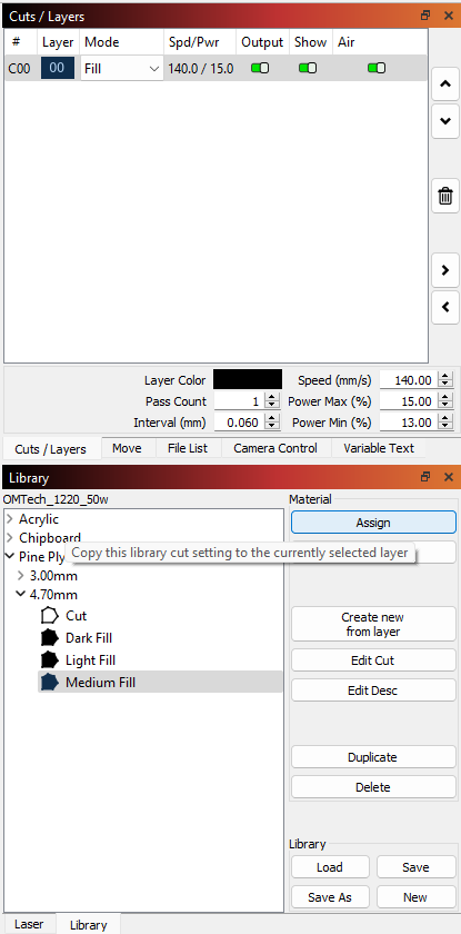
In the Library Tab, select a material from the list and expand the options. Keep expanding through the material thickness until you reach the designated laser parameter you wish to utilize, and click Assign.
Here I have selected 4.7mm Pine Plywood.
This is the average thickness of the 5mm Plywood Underlayment sold at HomeDepot and Lowes.
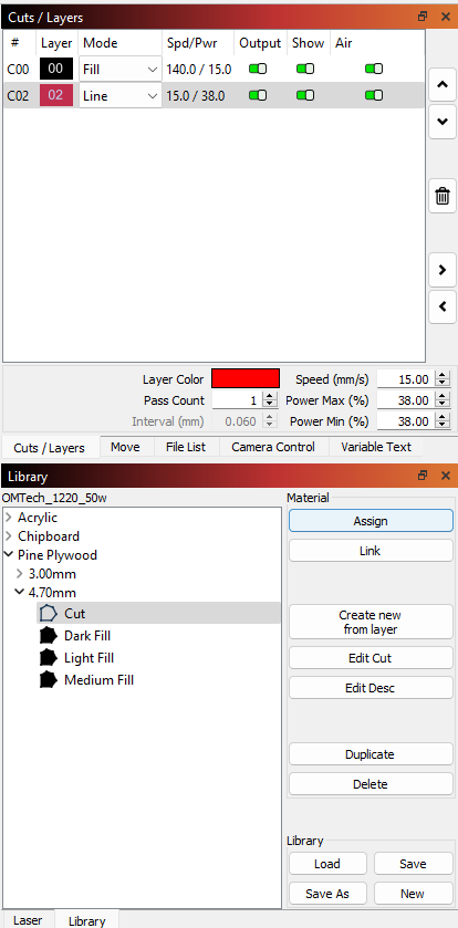
You should see the cut parameters of the layer change to that which is set in the Library.
The Medium Fill option for this Pine Plywood sets the mode to Fill, which is a back and forth motion with the speed set at 140mm/second at a range of 13%-15% of the Laser’s Maximum power.
Select the outer lobed section of the design, and assign it to Layer 02 – Red.
In the Material Library, select the Cut parameter, and select Assign to change the Layer 02 – Red settings to that needed to cut through the material.
Here you can see the settings are changed to a mode of Line, with a speed set to 15mm/second with the power set to 38% of the laser’s maximum power.
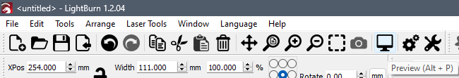
With the setup in the program done, we can preview the cuts and get the approximate cut time for the job.
The button for this is in the top menu, and looks like a TV or Monitor. The Keyboard Shortcut is Alt+P.
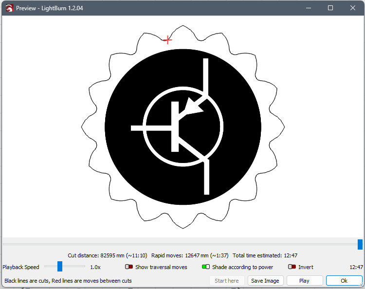
The preview window will show you how it expects to run the job. You can even show a movement simulation of the job by pressing the play button at the bottom.
The black areas of the preview indicate where the machine expects to run the laser with its power on.
This preview looks correct for what we are trying to make.
The estimated time for this engrave and cut job is 12 minutes and 47 seconds.
Setting up the Machine
Now we need to setup the machine and our material.
First, make sure the power strip plugged into the wall is on.
Then, twist the red EStop button clockwise on the top of the machine to unlock it.
Next we need to flip the switch for the main power to the machine.
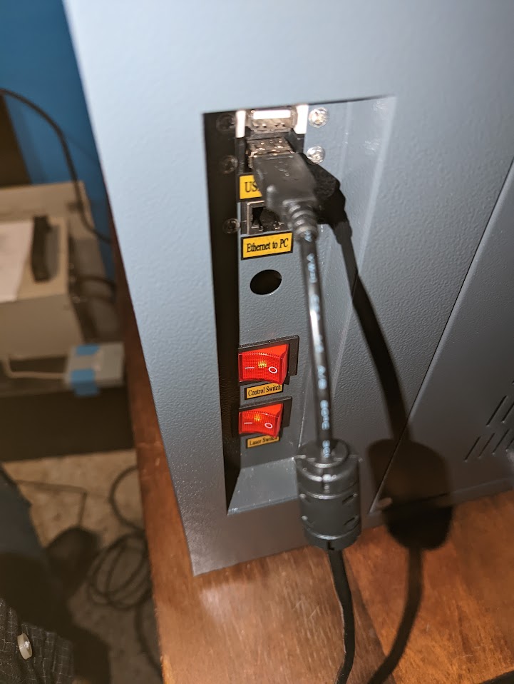
On the right side of the machine, near the front is a series of switches and ports.
For now, turn on the switch labelled “Control Switch”.
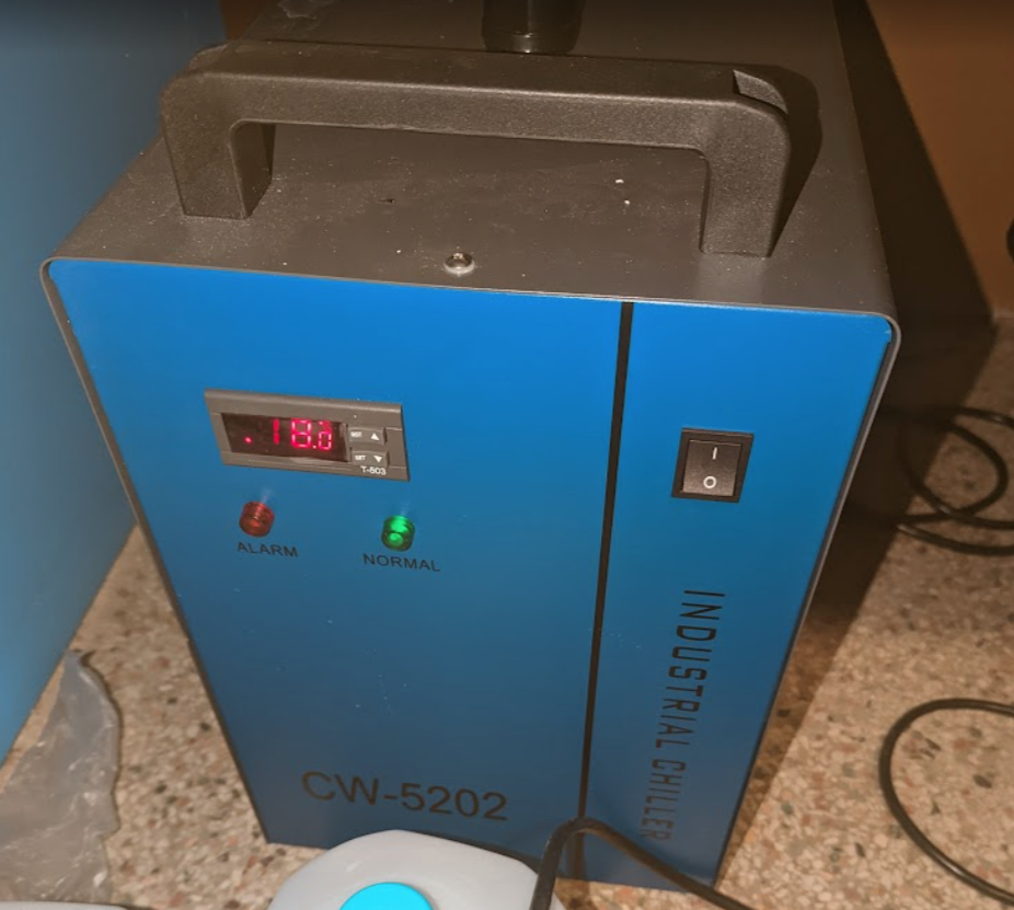
When you turn this switch on, lights inside the machine will turn on, it will automatically home the X and Y axes, and will supply power to the water chiller, which should automatically power on and start circulating water. When the chiller is powered, it will usually chime with 2 series of 3 tones. That does indicate that it is powered on and chilling to the settings that have already been specified.
With the power on, verify that the exhaust fan in the back of the machine is running.
Also, verify that the air assist pump is running by placing your finger or a small strip of paper below the laser head nozzle to verify that air is coming out. The air assist prevents the parts from catching fire while being lased and pushes the ablated material out of the cut.

Next we need to setup our material to be cut on the laser.
The maximum cutting area on the laser is 500mm x 300mm, or about 20 inches x 12 inches.
The maximum stock material can be a bit bigger than that, at <insert measurement here>, limited by the leadscrews that hold the bed adjustment in place.
For this part, we need a chunk of stock material that is at least 4.5in x 4.5in, but having a bit of extra space will help with alignment.
Place the material on the bed, and do your best to align it to the movement of the X and Y axes.
Use the red dot pointer as a reference.
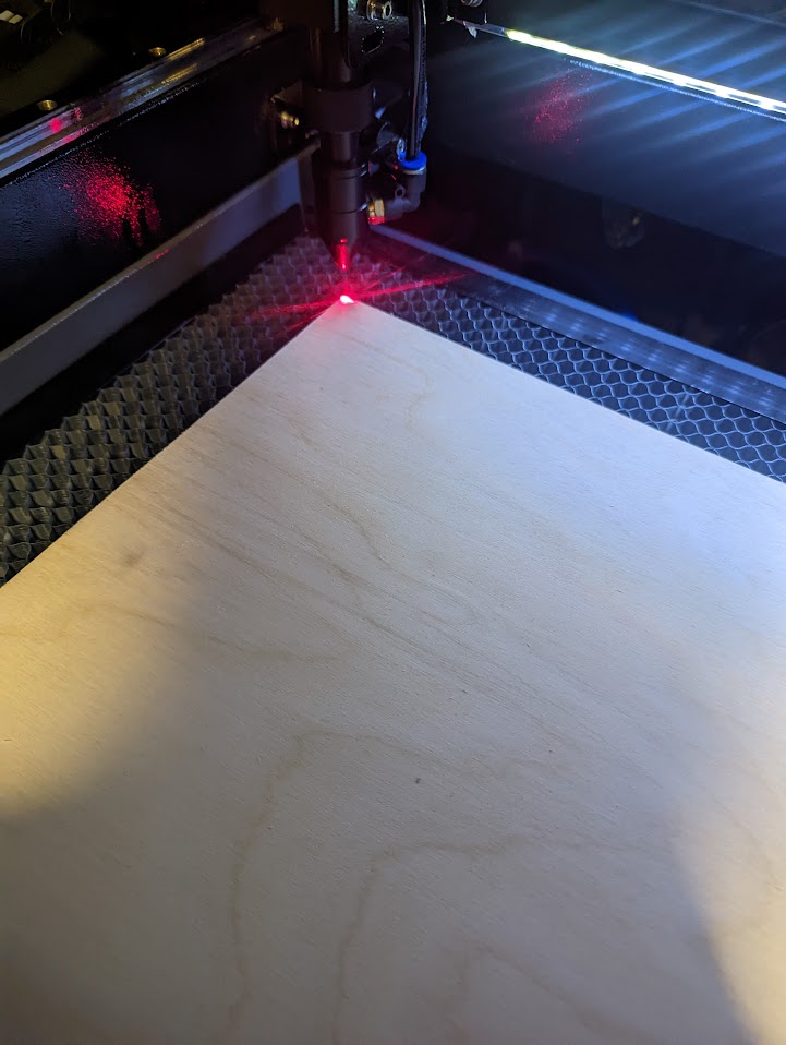
You can use the control panel on the top to move the X and Y axes to verify the alignment.
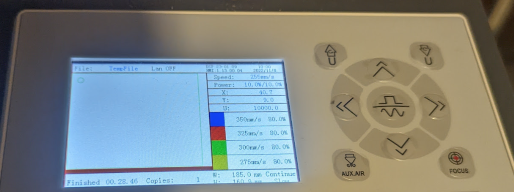
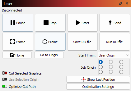
With the material aligned to your starting point, press the button on the control panel labelled “Origin”. This will tell the machine to start your job from this point.
This corresponds to the Job Origin option in Lightburn, when the Start From selection is set to “User Origin”
To make sure the material is the proper distance from the laser head, there is a knob on the front right section of the bed that allows you to raise and lower the bed.
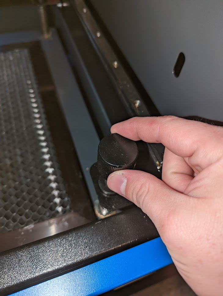
Getting the spacing between the material and nozzle is important. There is a spacer on the keychain for the machine that you can use to verify the spacing.
Turn it on its side, and slide it between the nozzle and your material.
Turn the knob so that the spacer is just captured by the nozzle. If you have the material too close, the spacer may crush into the material, or cause it to bend and be misaligned.
Verifying the setup
With the alignment done, and the job prepared, we can now verify that the material is in the proper place and the machine knows where to start by framing our job. This tells the machine to move around the outer extents of our job area so we can visually inspect our setup.
In Lightburn, click the Rectangular Frame button. This will move the machine in a rectangular shape over the bed.
The Freeform Frame button will draw the shape of the outer extents of our job, and is great for circular shaped objects that need to be precisely cut or engraved on a material.

With our material prepped, and the machine setup, we will follow through with the last of the safety checks and verify the job is ready to cut.
First, we need to make sure that the water chiller is on, and has reached the desired temperature of around 18 degrees Celsius or lower.
This temperature will fluctuate a couple of degrees as the job runs. The critical temperature is 22 degrees Celsius. Using the laser with the temperature above that will greatly reduce the lifespan of the Laser Tube.
Double check again that that air assist is on.
Once you are set, close the lid to the laser cutter. There is an interlock in place that will prevent you from running the laser with the door open, but like all things, safety checks like that can fail, so it is best to follow all the best practices for safety when using a laser cutter.
On the power panel on the right side of the machine, flip the switch labelled “Laser Switch” to On. This provides power to the laser tube.
Most jobs that fail to engrave are likely due to this switch not being turned on.
Running the Laser job
In Lightburn, press Start to begin the job.
If you intend to run this job multiple times, it is possible to send it to be stored on the Laser Cutter itself, but there is limited storage available for that purpose. For now, we will just start the job from the computer.
IMPORTANT!
Observe the job as it is happening. Verify that there are no flames coming from the material that are not being blown by the air assist. Small amounts of flames are expected as the material is being vaporized from the surface, and the vaporized material may be reignited by the laser.
If the job needs to be stopped in an emergency, press the E-Stop button.
This will immediately kill power to the machine and the chiller
Job Completion
When the job is complete, wait for the fumes from the cut to dissipate for a few minutes before opening the cover.
Open the cover, and remove your material and the parts from the cut job.
If you are done with the laser, turn the switch labelled “Laser Switch” to off.
Turn the switch labelled “Control Switch” to off.
Press in the E-Stop switch.
Turn the power to the main power strip off.
Clean up any extra dropped bits of material from bed.
Close the lid to the machine, and you are done.