Hackerspace Maker Coin – Fusion 360
Using this tutorial, you should be able to create the line drawings in Autodesk Fusion 360 that is used to create the Gainesville Hackerspace MakerCoin.
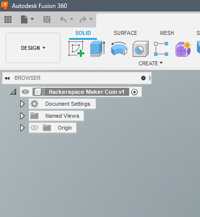
Create a new document
Create a new file in your working project. Call it whatever you’d like. Here I’ve called mine Hackerspace Maker Coin.
The Version Number will automatically increment as you save your progress
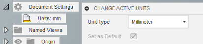
It will be easier if you set your document units to millimeters. If you do not wish to do so, make sure to type in unit qualifiers for measurements given in this tutorial.
Create a New Component
In the Solid Workspace, click Create->New Component.
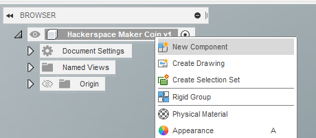
Alternatively, you can right click the document name, and select New Component
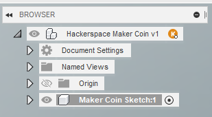
Name the new component whatever makes sense for you. Here I have named it Maker Coin Sketch. Click OK.
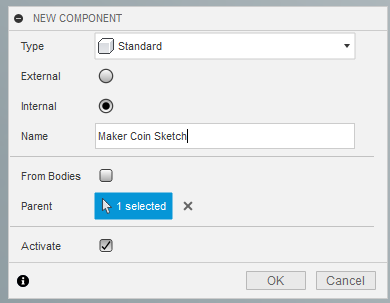
Make sure the newly created component is the Active Component. Active Components are noted by the radio selector being highlighted.
Create a new sketch
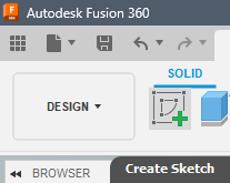
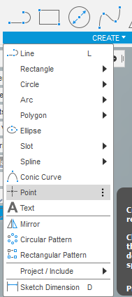
In the Create Menu, select Create Sketch
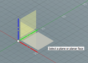
Select the XY Plane as your sketch plane.
This is the plane that you would see looking from the top down onto a surface.
Think looking down at a flat sheet of paper on a dining room table.
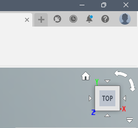
If your view is not automatically oriented into that top down view, select Top from the View Cube in the top right corner of your workspace to orient your view.
Create reference items
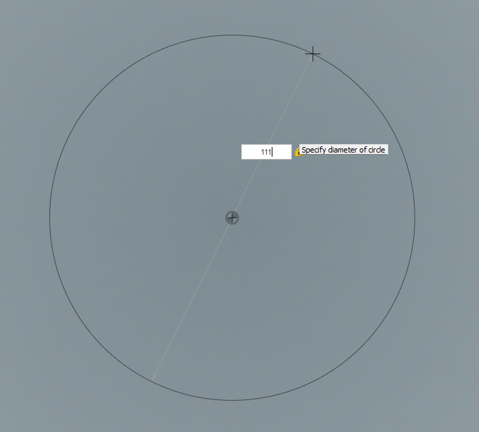
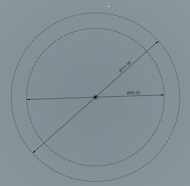
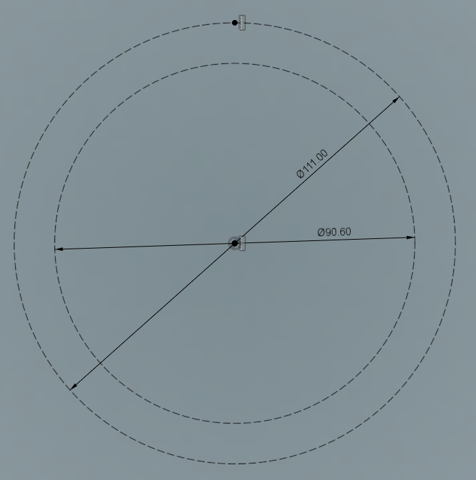
Create a Circle with the center being the origin target of your workspace.
Make it 111mm in diameter.
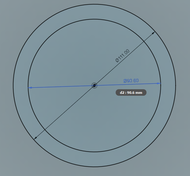
Create a second circle with the center also being the origin target of your workspace.
Make it 90.6mm in diameter
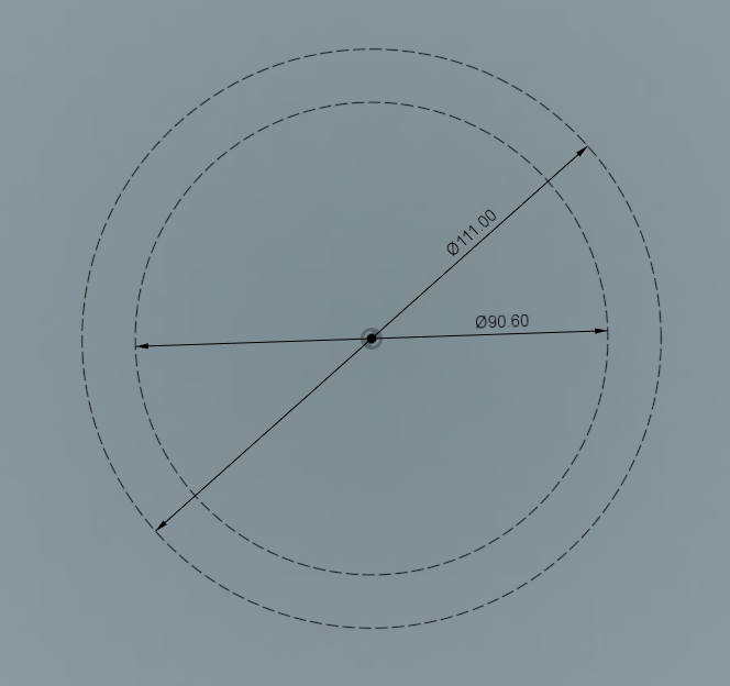
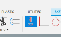
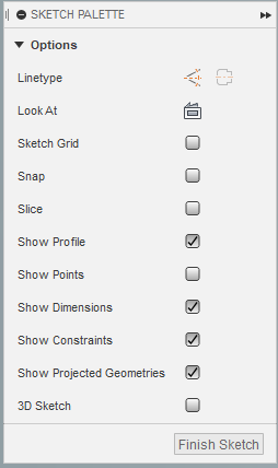
Select the Circles you have created, and select the Construction Linetype in the Sketch Palette. The keyboard shortcut is X
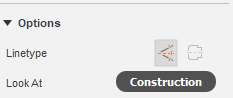
When the lines are situated as a construction line, it will show as dotted lines
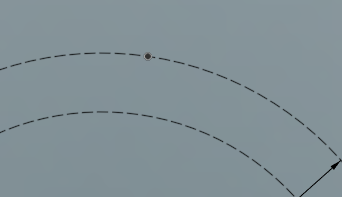
Create a point near the top of the outer circle, by selecting Create->Point from the menu.
Select a spot on the canvas near the top of the outer circle
We need to make sure this point is always touching the outer circle we created.
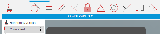
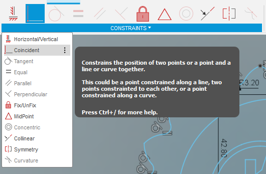
From the Constraints Menu, select Coincident
Create a Coincident Constraint between the point created and the outer circle.
We also need to make sure the point is always at the top of our circle.
Select the Horizontal/Vertical Constraint from the Constraints Menu.
Select the point we created, and the origin target on the canvas.
This will snap the point to always be in the vertical (Y-Up) position of our sketch, because the point was closer to the top of the circle. If the point you created snapped to the side of the circle, press Undo, move the point closer to the top of the circle, and try again.
We can see the constraint is applied by the little white vertical constraint icon next to the point we created and the origin point.
Create the Lobes
Now we will create an Arc that is one half of a lobe of our MakerCoin.
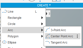
From the Create Menu, select Arc->Center Point Arc.
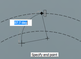
Select your first point to be somewhere under the 2nd Circle.
Select the second point to be the Constrained Point we just created.
Select the 3rd point to be somewhere off to the left of that constrained point, and lower than the smaller reference circle. The angle and dimensions do not currently matter.
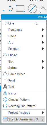
We will now apply explicit dimensions to our sketched arc.
From the Create Menu, select Sketch Dimension.
The Keyboard Shortcut for that is D.
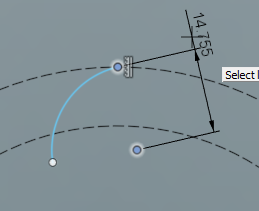
Select the center point of the arc we just created, then the constrained point at the top of our reference circle.
Fusion has two ways of considering dimensions. Normal to the objects you are assigning the dimensions to, or normal to the XY dimension of your document. Here we want the dimensions to be normal to the objects.
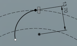
Here is what it looks like when the dimensions are normal to the XY Plane.
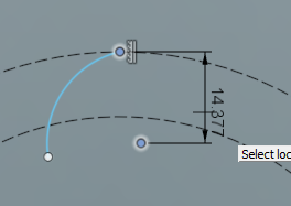
Set the dimension to 13.7mm
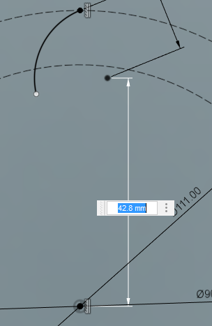
Dimension the arc center point to the origin point.
Here we want the dimensions to be normal to the XY plane.
Set the dimension to 42.8mm
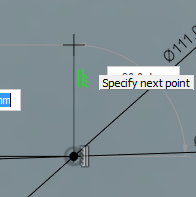
Draw a line vertical from the origin point. The size does not matter, as it will be for reference in a future step.
You can see constraints may get automatically applied as you sketch by the green sketch constraint icon next to the item being created.
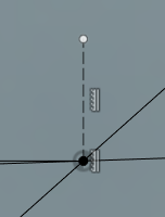
Convert the newly created line into a construction line.
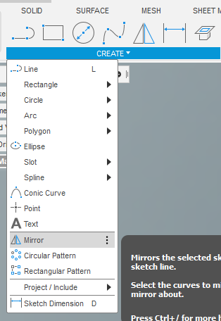
To create a mirror of sketch objects, from the Create Menu, select Mirror.
Select the sketch lines you would like to have mirrored.
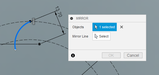
Click the Select option next to Mirror Line, then select the vertical construction line we just created.
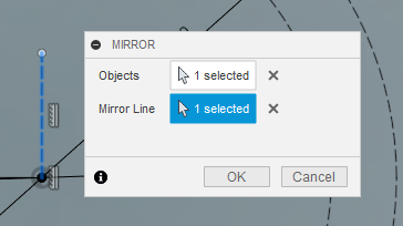
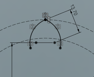
Click OK, and the sketch lines are mirrored.
Mirrored sketch lines are indicated by the Mirror Constraints.
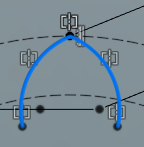
Hold Control or Shift, and select the 2 arcs that make up the lobe.
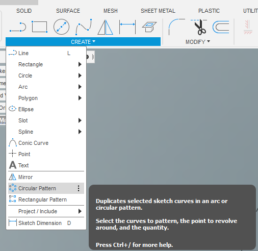
From the Create Menu, select Circular Pattern.
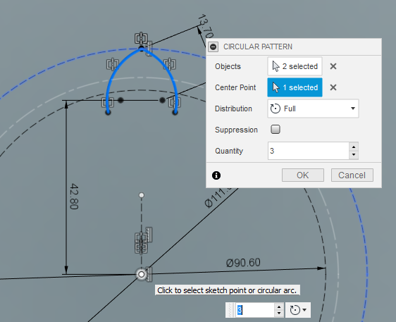
To create the pattern, you must now select the point which you want the pattern to rotate around.
Select the origin point, or you may also select one of the reference circles.
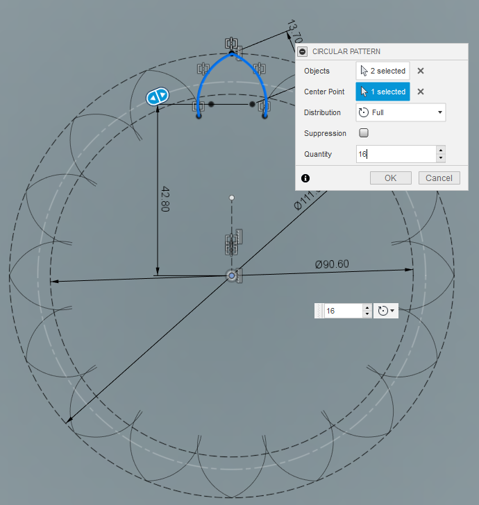
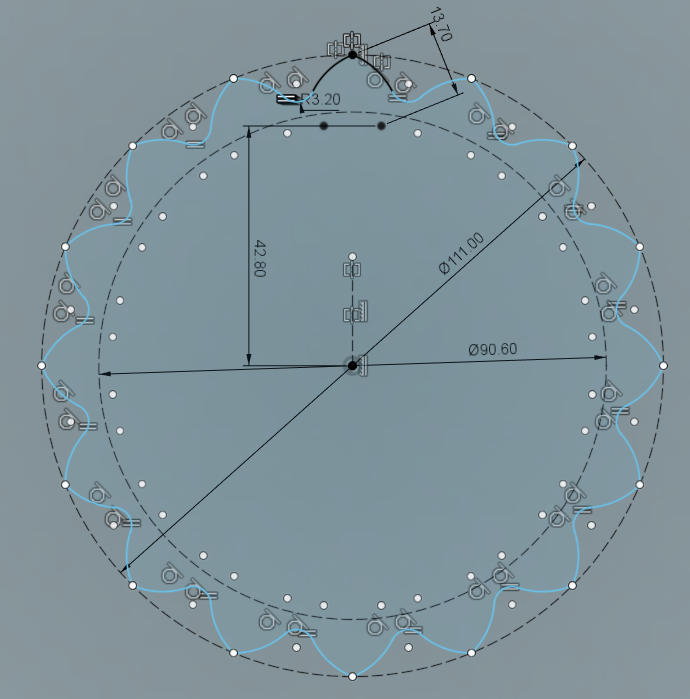
Set the Quantity to 16, and select OK.
Modify the Lobes
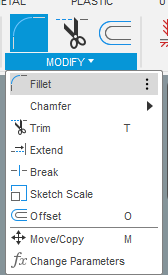
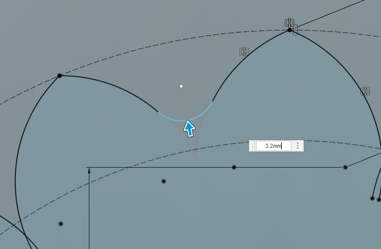
We now need to create fillets between the lobes.
Select from the Modify Menu->Fillet
Select the left arc of the top lobe, then the right arc of the lobe adjacent to the left. Set the dimension to 3.2mm.
Select the left most arc of that second lobe, then the rightmost arc of the adjacent lobe to the left. Continue this all the way around the sketch until the lobes all have fillets between them.
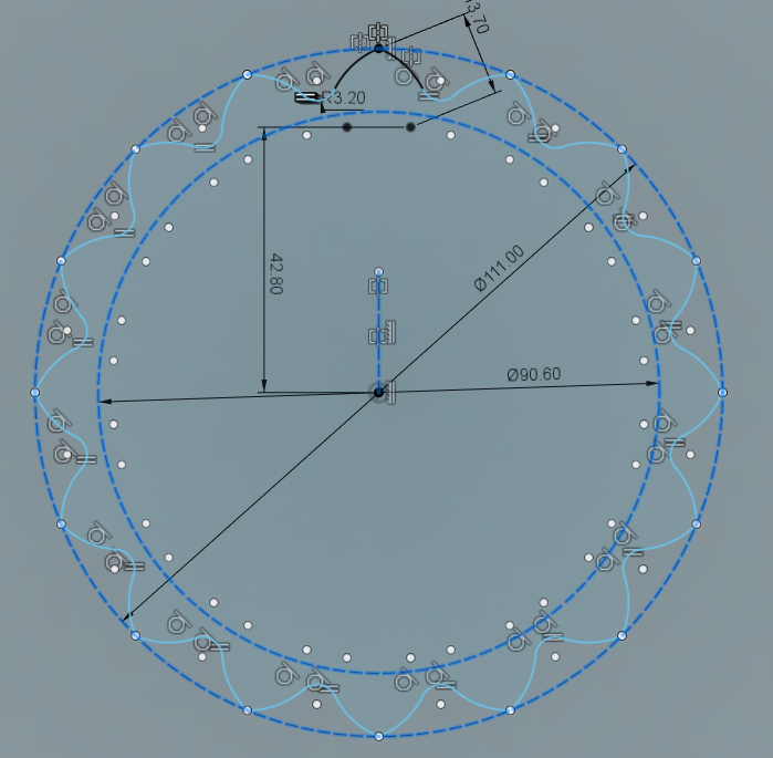
Clean up the reference sketch items
Holding Control or Shift, select the 2 reference circles, and the vertical construction line.
We no longer need them, so press delete on your keyboard to have them removed.
Insert the Hackerspace PNP Logo
Next we need to insert the Hackerspace PNP Logo.
You may download the DXF from: https://gainesvillehackerspace.org/static-content/HackerspacePNPLogo.dxf
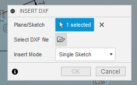
From the menu, select Insert->Insert DXF
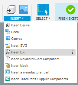
Click the item for Select DXF File.
This will bring up the file picker for you to select the downloaded DXF file.
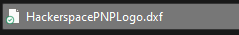
Select the HackerspacePNPLogo.DXF file.
Set the Units to Millimeter, and click OK.
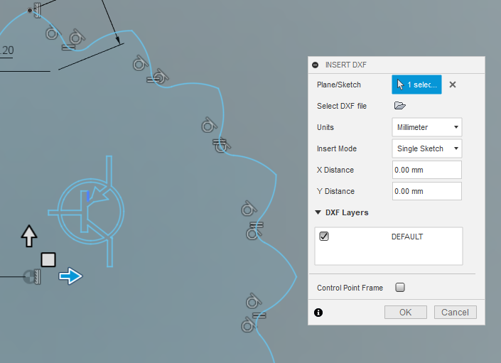
Select the imported PNP Logo by dragging a box around it from top left to bottom right. Try to avoid the origin token point if you can help it.
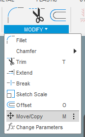
From the Modify Menu, select Move/Copy.
Drag the handles of the move selector until the PNP Logo is fairly centered in your design. Click OK to stop the move dialog.
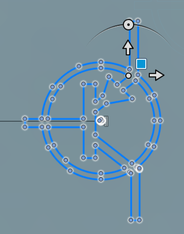
Select the PNP Logo again. This time, it will be impossible to avoid the origin point.
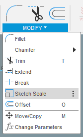
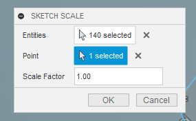
From the Modify Menu, select Sketch Scale.
We need to select the scaling reference point. Select the X next to Point, then select the Selection icon.
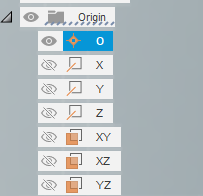
From the browser on the left, expand the tree for Origin under your Component. There will also be an Origin tree under the main design file.
Select the Eye icon to unhide it from view. With it visible, it can now be selected.
Select the O from that list to assign that origin point as the scale point for your Sketch Scale command.
Set the Scale Factor to 3.25, and click OK.
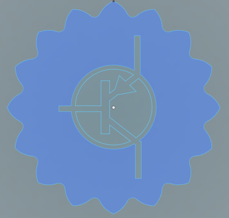
Finishing touches
Draw a circle around the PNP logo. Size and position do not matter yet.
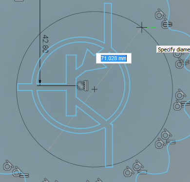
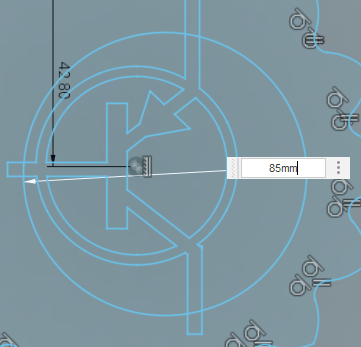
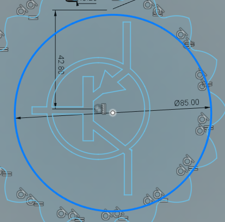
Select Create->Sketch Dimension. Select the circle you just created, and set the diameter to 85mm.
Select the circle we just dimensioned, and in doing so, notice a marker with the center of the circle appears. Select that center point.
From the Constraints Menu, Select Coincident.
Select the Origin Point from the browser again, and the circle will snap to be centered on that origin point.
Select Finish Sketch from the Sketch Palette to complete the sketch drawing.
Congrats!
You have completed the CAD portion of creating the Hackerspace MakerCoin!
The next steps are to decide how you want to make this coin a physical object:

Do you want to 3D Print the MakerCoin?
Do you want to CNC Cut the MakerCoin?
Do you want to make a Vinyl Sticker of the MakerCoin?