Hackerspace Maker Coin – Onshape
Using this tutorial, you should be able to create the line drawings in Onshape that is used to create the Gainesville Hackerspace MakerCoin.
Onshape is a Web Based 3D Parametric CAD software that can be used to make 2D and 3D shapes and geometry that can be exported and used with other various software and hardware for manufacturing. Check out www.onshape.com/en/products/free to see what features are available for the Hobbyist/Free license
Getting Started
Creating the Document
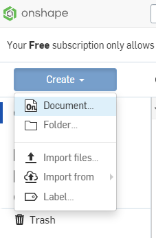
First, we need to create a new document
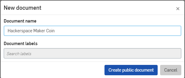
It will prompt for a name. Here I’ve called mine Hackerspace Maker Coin
Click Create Public Document.
One of the limitations to the free version of Onshape is all documents made with the free plan are searchable and publicly available to anyone using Onshape. This means anything that you make in Onshape is not saved as a private document. See https://www.onshape.com/en/products/free for more information on the limitations of the free plan.
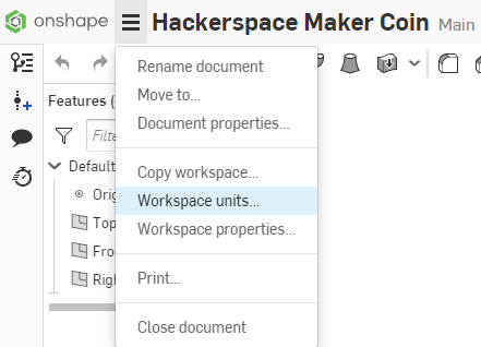
When the document is open, it is beneficial for this tutorial to use metric units. Click the 3-Bar Menu at the top next to the Document Name, and select Workspace Units from the Menu.
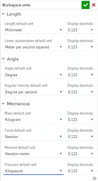
For the easiest time following the tutorial, set the Length default unit to Millimeter. Select the Check Mark at the top of the panel to accept the changes and close the dialog.
Starting the Sketch
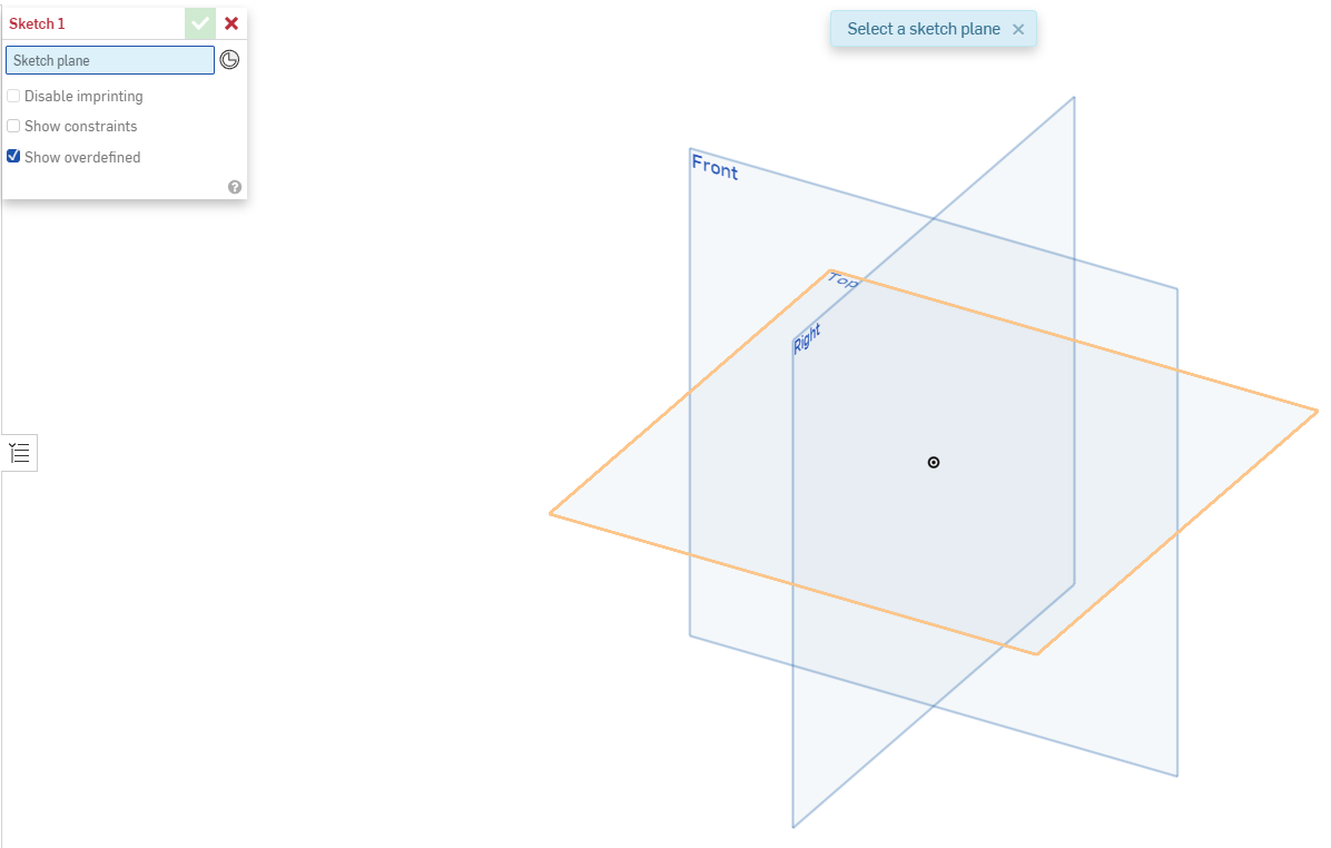
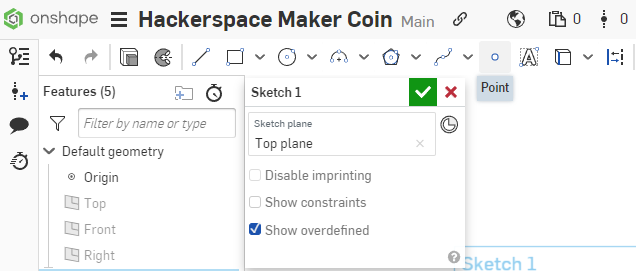
With the document open, click the Sketch Button to create a new sketch.
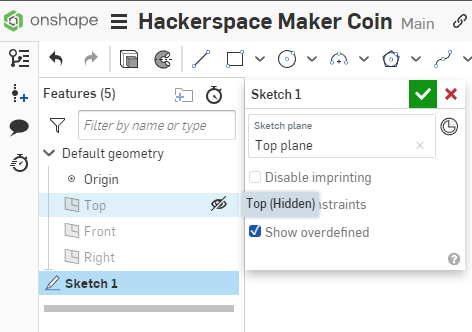
Select the Top Plane to set the plane to reference the sketch from.
The Top Plane will be highlighted with a Yellow/Orange highlight before you click on it to indicate this is the plane you will be selecting.
The Sketch Dialog will indicate that you have selected the Top plane for your sketch reference, and the toolbar across the top will change to sketch tools.
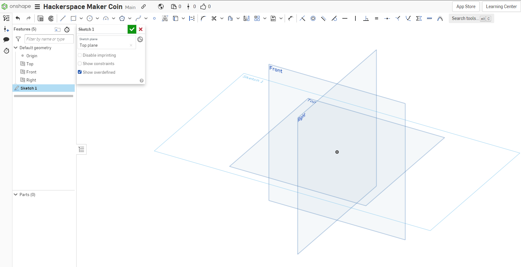
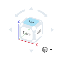
Select the Top section of the View Cube to orient the view of the workspace top down to the sketch for a better working angle.
In the Features Browser on the Left side of the workspace, hover over the Top, Front, and Right planes shown to show the Visibility Icon, an eye, and click it to toggle the visibility to Off. This clears up the view to make it easier to work.
Leave the Origin point visible, as we will reference it in future steps.
Creating the first circle
For the first step, we will need to create a Circle.
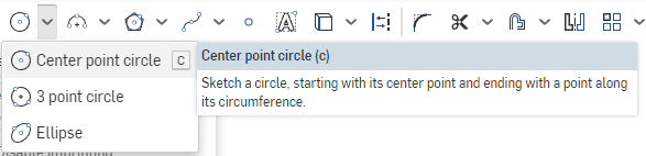
Select the Center Point Circle tool from the Sketch Bar. The keyboard shortcut is C.
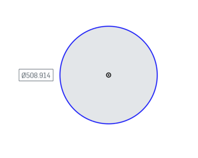
Select the Origin Point in the View to select the point to start the circle. Move the mouse out away from the center to draw a circle on the Sketch Plane. It will display the size of the circle as you are making the shape. The size currently does not matter, as we will set that in the next step. Click to set the circle in place.
Next we will dimension the outer circle to be the correct size.
Select the Dimension tool from the Sketch Toolbar. The keyboard shortcut is D.
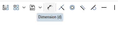
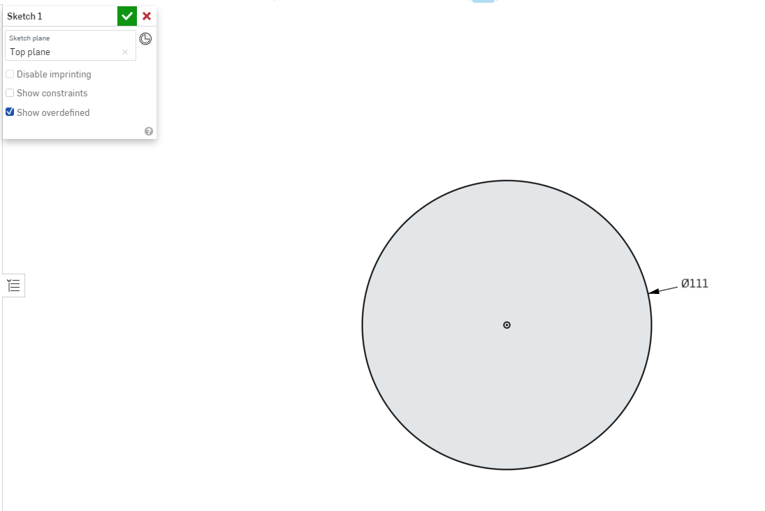
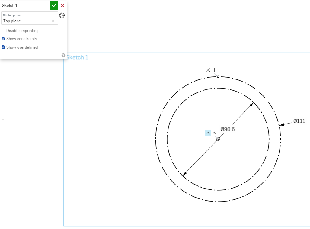
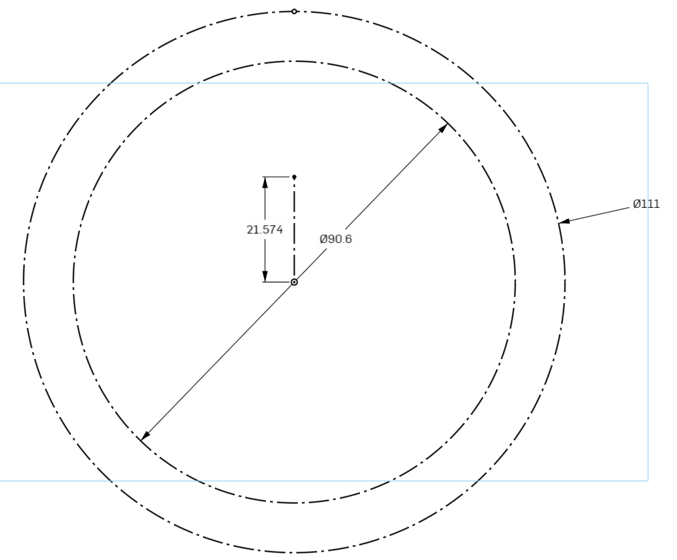
Select the outer ring of the circle to select it, and drag a little to the side and click to place the dimension tool. It will now prompt you to enter the dimension you are looking to set. Type 111mm to set the circle size to that, and hit enter on the keyboard.
If the circle is too small to work with on your screen, use the scroll wheel on the mouse to zoom in until the size is comfortable to work with.
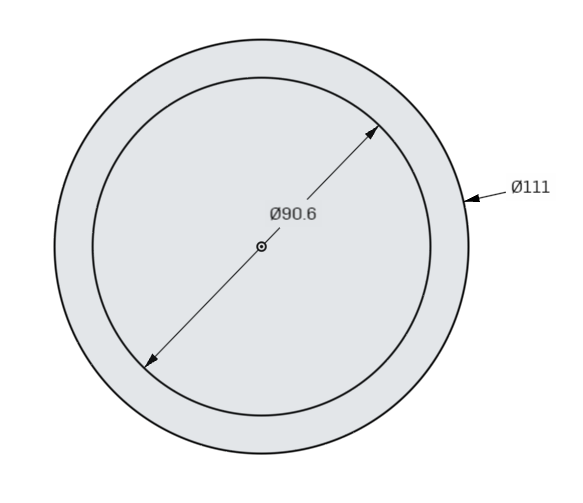
Creating the Second Circle
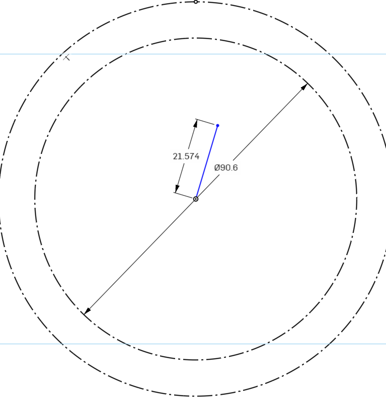
Create a second circle using the same origin point as the first, and dimension it to 90.6mm.
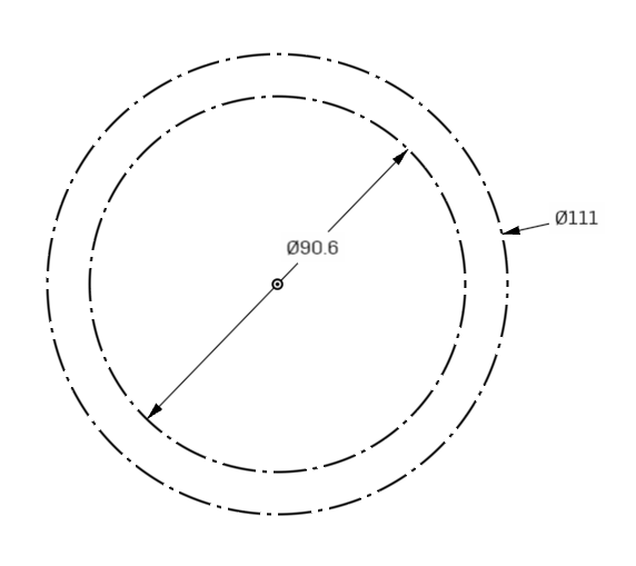
These circles will not actually be for the shapes we wish to create, but are reference geometry for future steps. To indicate that they are reference, we can select the circles (Hold Shift and click the edges of the circles until they are both selected) and click the Construction Button in the Sketch Toolbar. The keyboard shortcut is Q.
The circles we drew will change from solid lines, to dotted lines. This means they are for reference only, and cannot be used as a shape for creating 3d geometry.
Next we will create reference points on the circles for more future geometry.
Select the point tool from the Sketch Toolbar.
Select a spot on the 111mm circle near the top. The circle will highlight Yellow/Orange to indicate that you want to create a point that resides on the line. The point will be highlighted in blue to indicate that the position of it can still be moved.
We will use sketch constraints to force the position of the point to be vertically aligned over the origin point.
Select the Vertical Constraint from the Constraints section of the Sketch Toolbar. The keyboard shortcut is V.
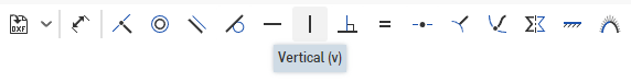
Select the point we just created, and the origin point to force the alignment of the sketch point.
The point will turn black to indicate that it is locked in place and can no longer be moved or positioned.
To view the applied constraints, in the Sketch1 Dialog, click the checkbox for “Show Constraints” to visibly show the applied constraints.
Here we can see that the point we created has 2 constraints applied. The first is a coincident constraint, which tells Onshape to make sure the point always overlaps on the circle, and the second is the vertical constraint we just applied.
You can leave the constraints visible if you wish.
Creating the Lobes
Next we will create the geometry for the lobes.
To start, let’s create a new reference line at the origin.
Select the line tool from the Sketch Toolbar. The Keyboard shortcut is L.
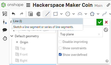
Select the origin point at the center of the circle for the start of the line, and a second point above the line to set the end of the line. The length and position do not matter, so long as it is above the origin point. When you have clicked to set the line, press Escape on the keyboard to finish drawing a line.
We will then constrain the line using the Vertical Constraint to force it to be vertical.
Set the line to be a construction line.
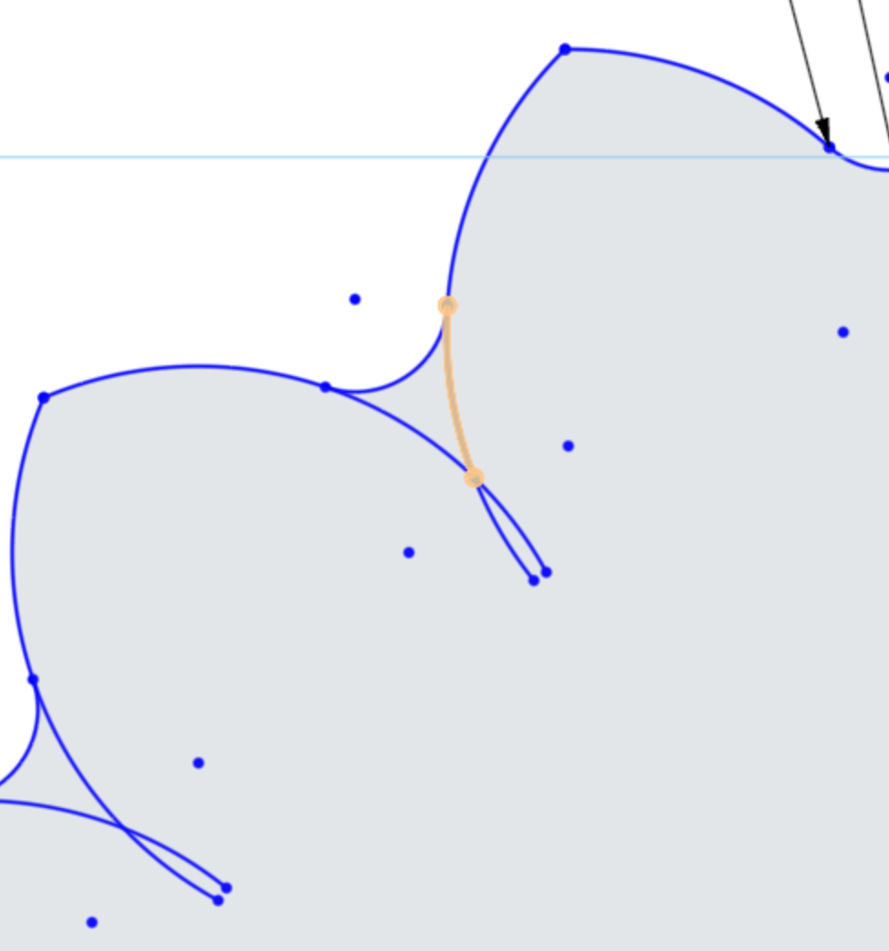
For the lobe, we need to create an Arc that starts at the point we constrained and sweeps down to the left.
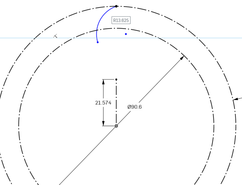
To start, Click the Center Point Arc tool from the Sketch Toolbar.
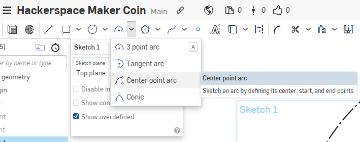
It will want you to place the center point of that Arc. Select an empty place in your sketch below the inner circle, off to the right of the centerline slightly. Again, positioning will be constrained later.
For the starting point of the Arc, select the point that we constrained on the outer circle.
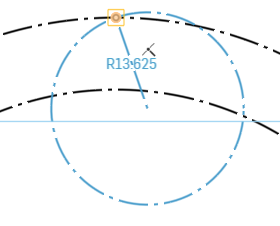
For the ending point, select a location off to the left of the starting point, below the inner circle.
Next we need to apply constraints and dimensions to this arc.
Onshape has two ways of considering dimensions. Normal to the objects you are assigning the dimensions to, or normal to the XY dimension of your document. Here we want the dimensions to be normal to the objects.
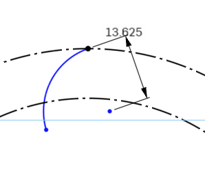
Here is what it looks like when the dimensions are normal to the XY Plane.
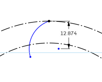
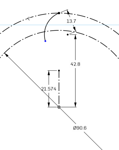
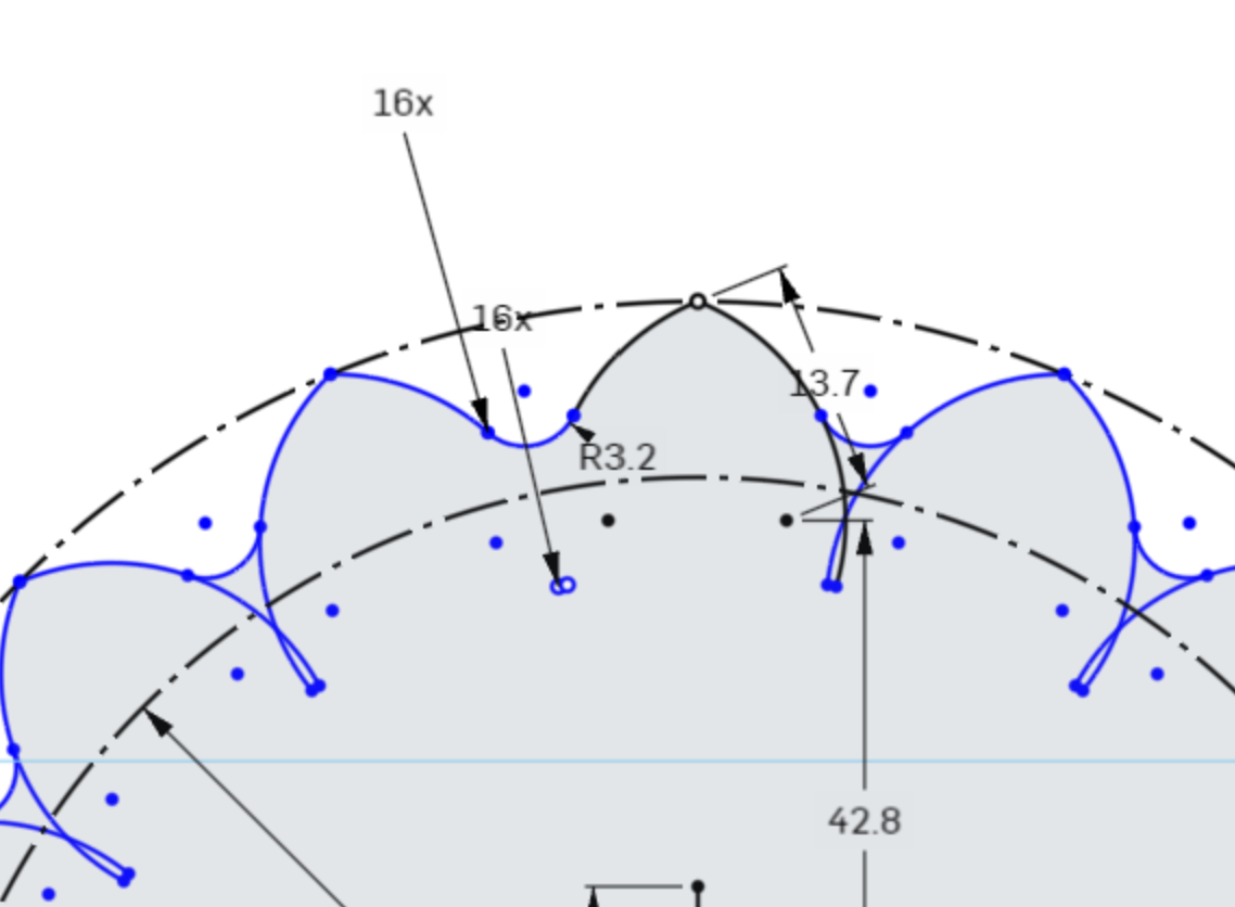
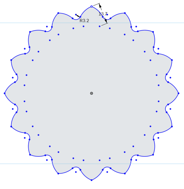
Select the Dimension Tool from the Sketch Toolbar, and select the top point of the Arc, and the center point that is off to the bottom right. Move the mouse pointer to the right, and slightly up to tell the dimensioning tool to be normal to the object.
Set the dimension to 13.7mm
Next we need to dimension the arc’s center point to the origin point.
Select the Dimension Tool again, select the Arc Center Point, and then the Origin Point in the middle of the circles.
Here we want the dimensions to be normal to the XY plane.
Set the dimension to 42.8mm
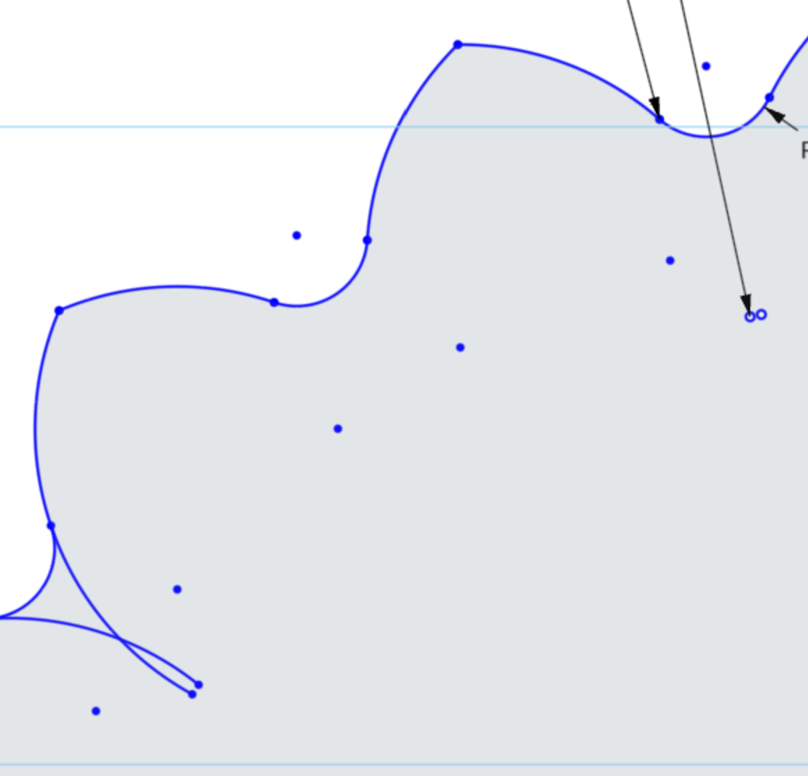
Now we will mirror this Arc using the vertical construction line we created earlier
Select the Arc line, and click the Mirror Tool in the Sketch Toolbar. A prompt at the top asks you to select the mirror line. Select the vertical line coming from the center point of the circle.
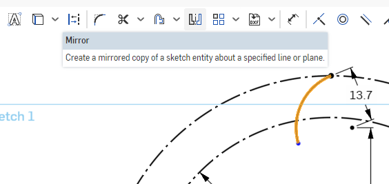
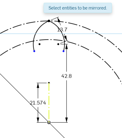
The prompt asks you to select entities to be mirrored, so if there were any other sketch items to mirror, you could select them now.
For now, we see that the Arc is mirrored and connected to the vertically constrained point on the outer circle. Hit Escape on the keyboard to finish the mirror tool.
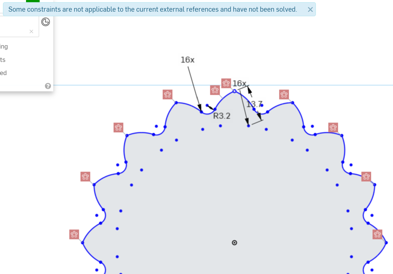
Next, we need to make copies of this lobe all around the edge of the circle to create a round object.
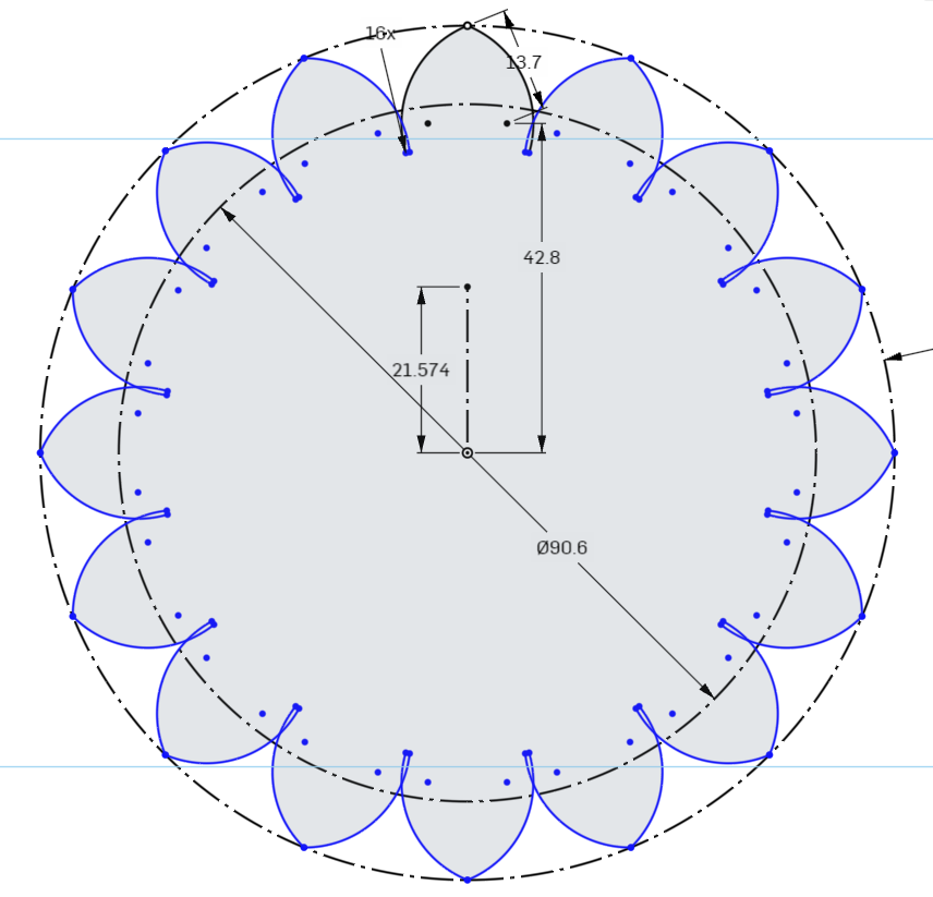
Select the Circular Pattern tool from the Sketch Toolbar.
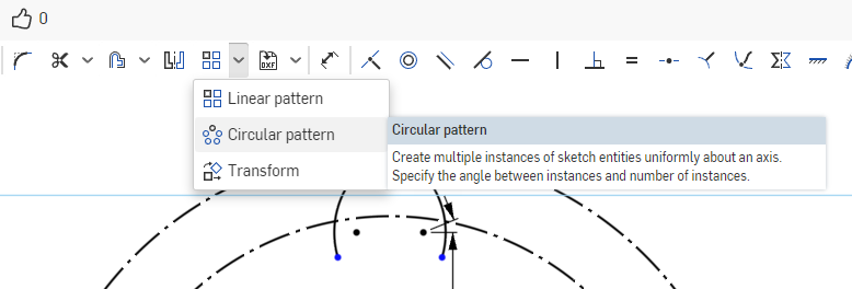
Select the 2 arcs we created in the previous step. To the left of the leftmost arc we selected, we will see the quantity counter for our pattern. Double click it to change the quantity, and set it to 16. Onshape should preview the lobes for you. Press Enter on the keyboard if it looks correct to you, and the lobes should be created.
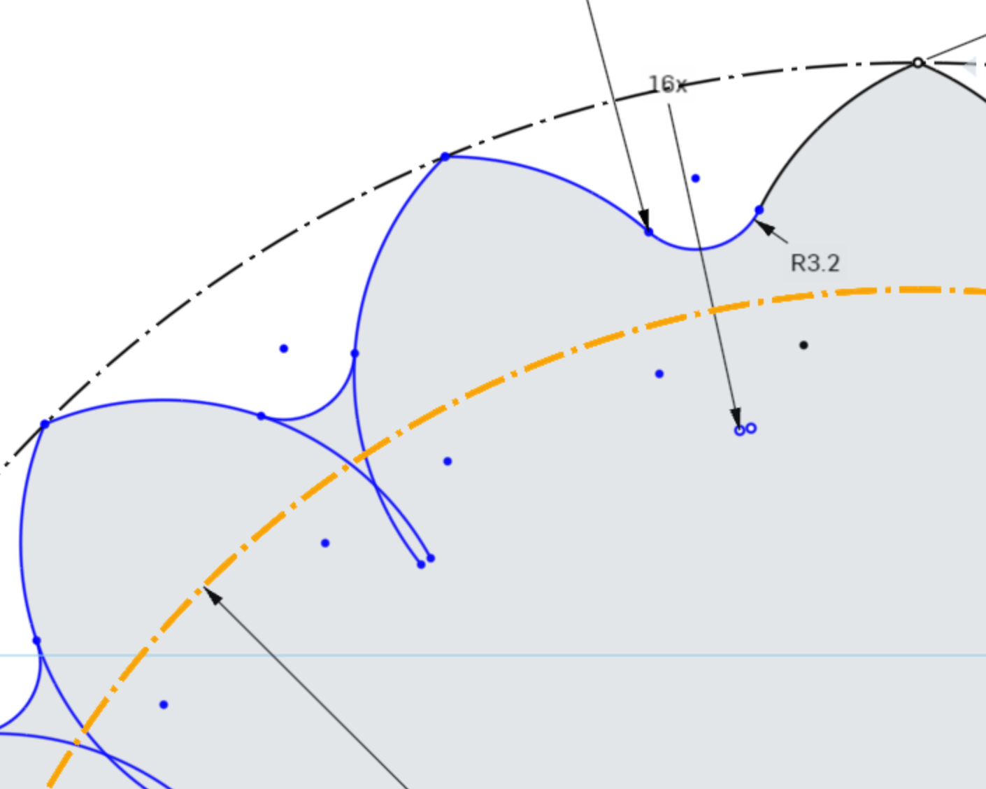
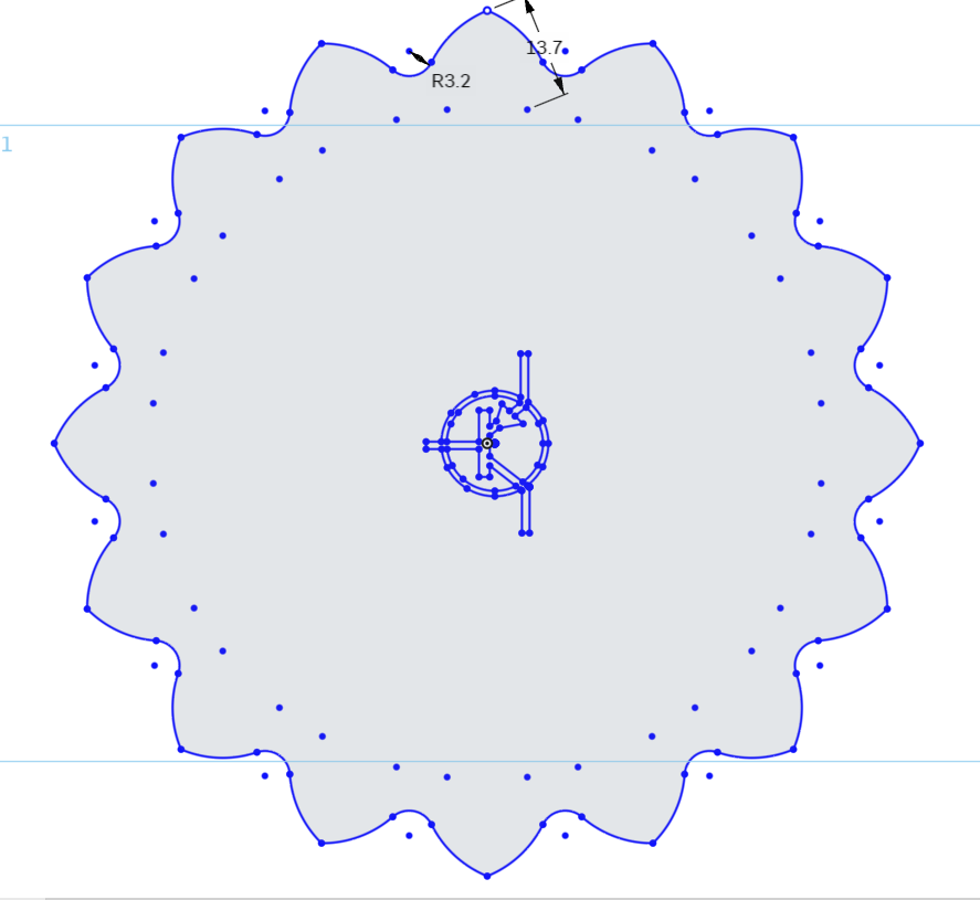
Next, we will add some detail between the lobes with Fillets, small tangent arcs that connect the lobes.
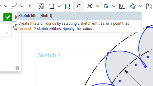
Select the Sketch Fillet tool from the Sketch Toolbar. The keyboard shortcut is Shift+F
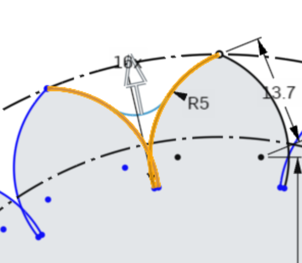
Select the leftmost line of the top lobe, and the rightmost line of the lobe directly to the left of it. The lines will highlight, and a fillet will show on the sketch.
Double click the Radius dimension for the fillet, in this screenshot it is R5, to open the dimension entry dialog.
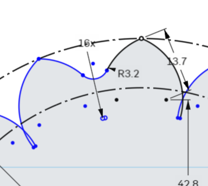
Enter 3.2mm for this dimension and press enter on your keyboard.
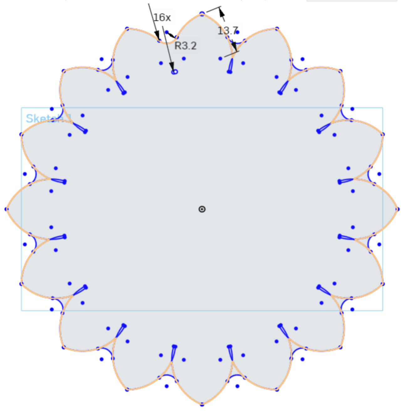
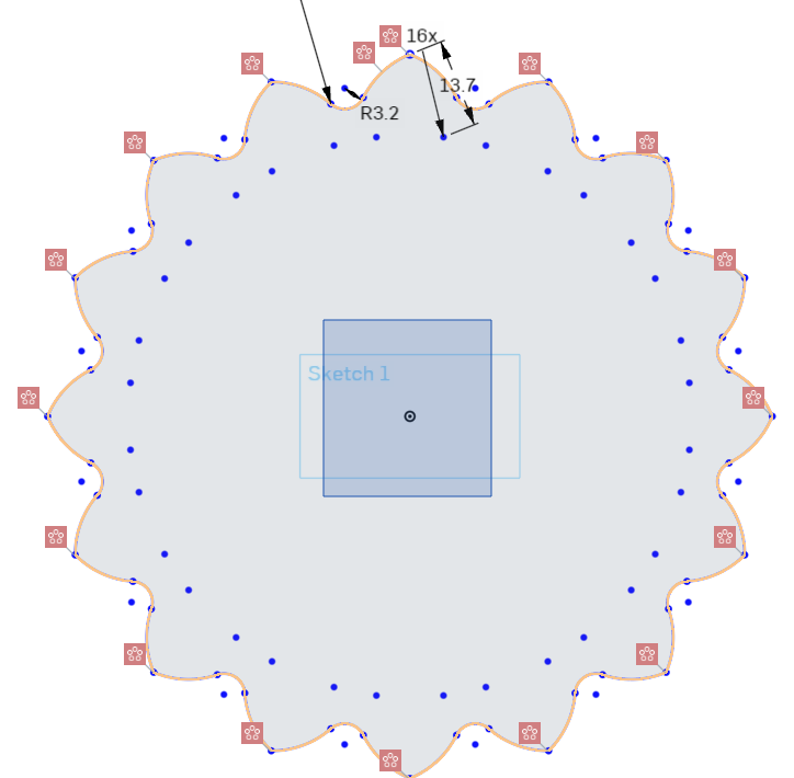
To not have to perform the previous steps 15 more times, we can create a circular pattern of the fillet around the center of the sketch.
Click the Circular Pattern Tool, select the fillet we created, and set the pattern instance counter to 16.
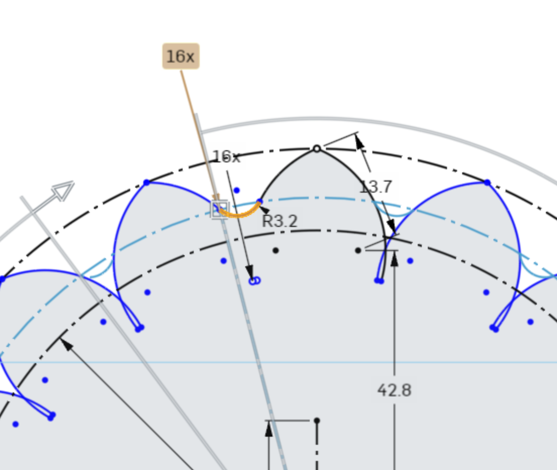
Press Enter on your keyboard to confirm the pattern.
Cleaning up Sketches
Using the pattern tool here did not clean up the extra sketch geometry that the first Fillet command did, so we must clean up the lines manually.
First, select the inner construction circle, and press delete on your keyboard to delete the construction circle.
Delete the outer construction circle, and the vertical construction line.
Next, we will use the Trim Tool in the Sketch Toolbar to delete geometry up to intersecting sections of the geometry.
The keyboard shortcut is T.
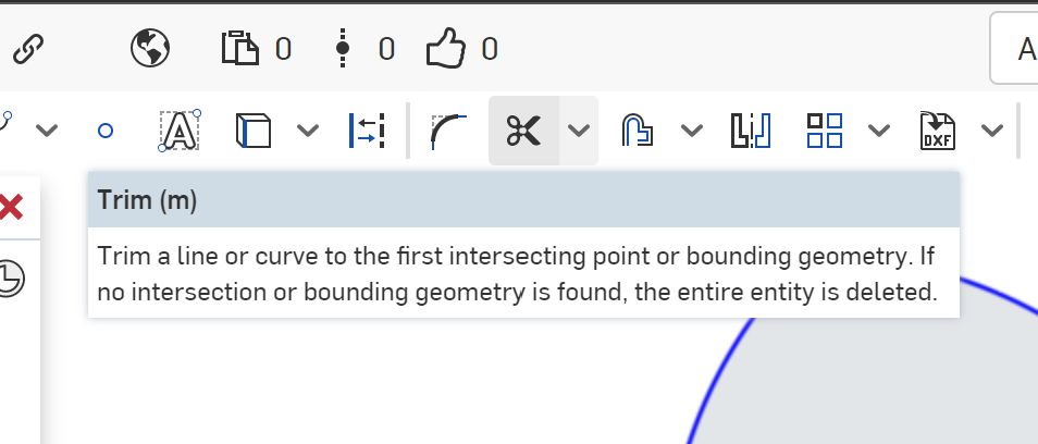
With the Trim Tool selected, click the arc lines that are in the interior of the maker coin sketch.
Eventually, you will trim up the unneeded Arc geometry that is no longer needed.
As you trim the lines, you may see that the lines or constraints may show as red, indicating that the reference points for the constraints and dimensions are missing. This is fine for our purposes, and we will correct this in the next step.
To cleanup the errored constraints, drag a selection box around the center point at the Origin.
Press delete on your keyboard to remove the unneeded center points, which should clean up the errored constraints.
Importing Geometry
Next, we will need to import some pre-created sketch geometry to create the Hackerspace’s PNP Transitor Logo inside of our Makercoin.
The file can be downloaded from https://gainesvillehackerspace.org/static-content/HackerspacePNPLogo.dxf
Once the file is downloaded, click the Insert DXF or DWG button in the Sketch Toolbar.
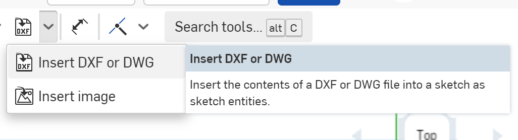
At the bottom of the menu that pops up, click the Import Button
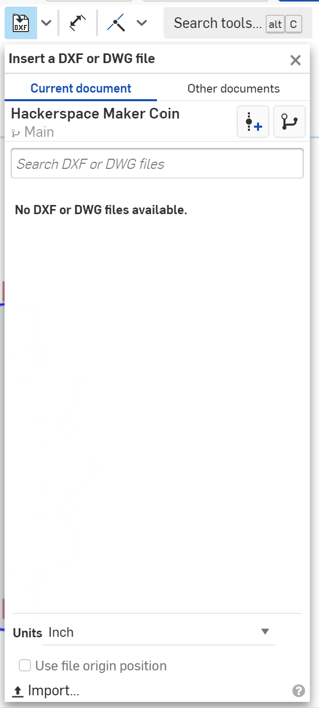
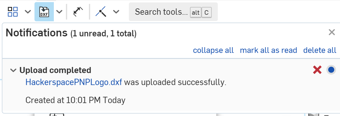
Select the HackerspacePNPLogo.dxf file you downloaded, and click Open.
You will soon get a notification from Onshape that the HackerspacePNPLogo.dxf file was successfully uploaded.
Set the units at the bottom to Millimeters, and click the HackerspacePNPLogo
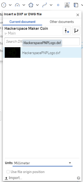
The logo should be imported, and placed very close to the origin point.
Now we need to resize the imported logo.
Drag a selection box around the imported logo to select it.
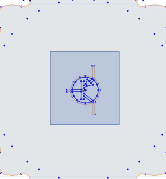
In the Sketch Toolbar, select the Transform Tool.
This tool allows us to manipulate sketch items, such as scaling, rotating, and moving points and lines.
Dragging the vertical arrow moves the selected sketch items straight in the Y Axis
Dragging the horizontal arrow moves the selected sketch items straight in the X Axis
The Square Move icon allows you to move the sketch items in any axis.
The circle with arcs next to the Horizontal Translation is the rotation tool. The rotation tool will rotate the sketch objects from the point of the translation origin, the circle where the X and Y translation arrows meet.
Dragging the translation Origin point will change where the translation command starts from. You can drag this origin point to anywhere in the sketch you wish.
Finally, the triangular icon pointing up and to the right is the Transform Scale.
With the tools explained, we need to set the origin of our tool to roughly the center of the logo, and scale the imported PNP logo.
First, drag the Translate Origin point to near the center of the PNP Logo. There is a series of points roughly collected together near the center, so that is a good place to put the Translation Origin.
Next, drag the Scale Translate arrow to bring up the Scale Multiplier.
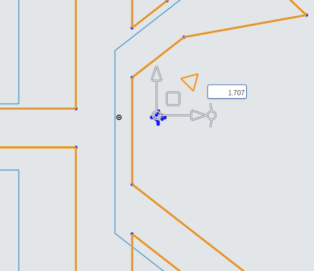
In the Scale Multiplier, enter 3.25 to scale the PNP Logo to the proper size.
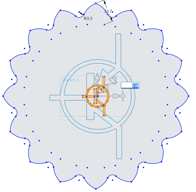
In an empty area of the sketch, left click to confirm the completion of the Translate Tool.
Finishing Touches
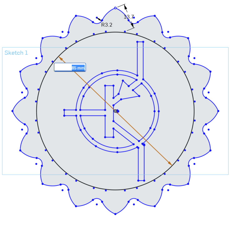
For the finishing touches, we will place a circle around the PNP Logo.
Select the Circle Tool from the Sketch Toolbar, and place a Center Point Circle with the center point being the origin point of the sketch.

Dimension this circle to 85mm.
In the Sketch Panel, click the Green Box with the White Checkmark to confirm the sketch, and close out of Sketch Mode.
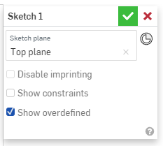
With the Sketch confirmed, the sketch will change to a different color, and the toolbar across the top will revert back to the 3D Design Toolbar.
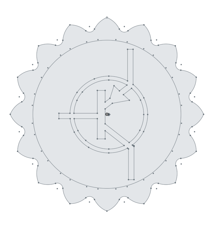
Congrats!
You have completed the CAD portion of creating the Hackerspace MakerCoin!
The next steps are to decide how you want to make this coin a physical object:

Do you want to 3D Print the MakerCoin?
Do you want to CNC Cut the MakerCoin?
Do you want to make a Vinyl Sticker of the MakerCoin?