Hackerspace Maker Coin – CamBam Plus
Using this tutorial, you should be able to create the line drawings in CamBam that is used to create the Gainesville Hackerspace Maker Coin.
Open the CamBam plus Application.
As of this writing, it is version 1.0.7364.41819
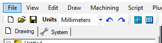
Set the document units to Millimeters
Using millimeters allows us easier access to some of the scaling options. Many manufacturing methods also default to using millimeters for units.
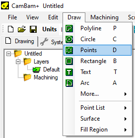
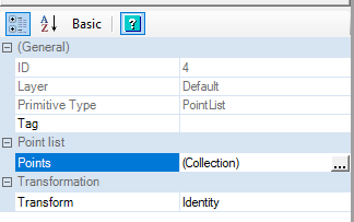
Create a point at the origin 0,0,0
Creating a point at the origin allows us to easily base some of our geometry around an easy to reference number (0,0,0) [That is, 0{zero} units away from the X, Y, and Z planes]
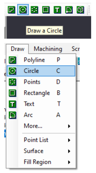
Select the button to draw a Point List from the toolbar, select it from the Draw Menu, or use the keyboard shortcut ‘D’.
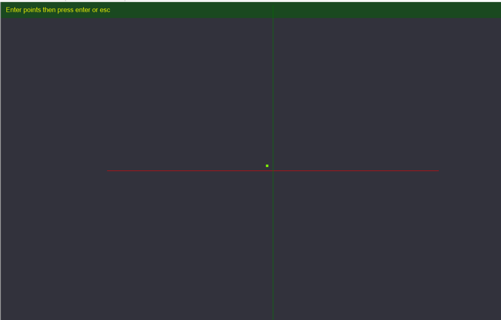
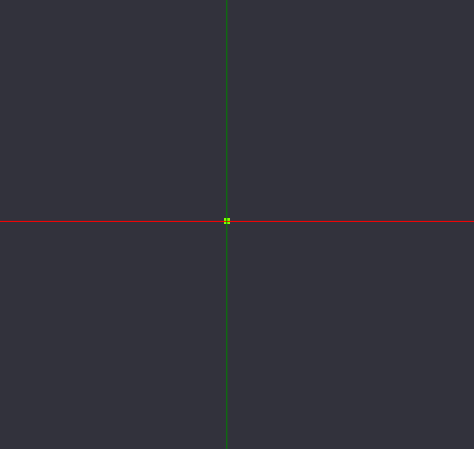
Place a point on the Canvas. It does not need to be at the exact center (where the Green and Red lines intersect). Press enter to complete your point placement.
Once the point is placed, on the details pane to the left, we see an object in the browser called “PointList”, and we can click the ellipsis(…) on the Point list property to pull up the coordinate box of the point we just placed.
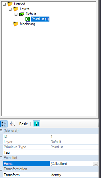
We can set the X, Y, and Z coordinates to 0, and click OK to save our changes.
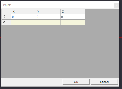
On the canvas, we can see the point we created has adjusted its location to the center.
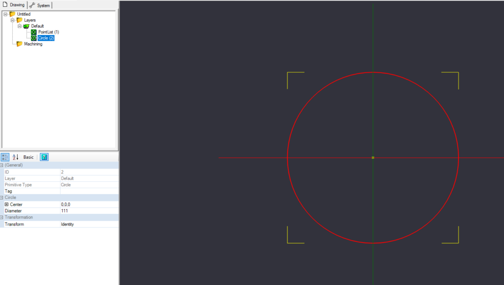
Create Circle, Diameter 111mm – Center at 0,0,0
Now we need to draw some reference geometry. Let’s draw the outer boundaries of the shape we will ultimately create.
You will need to draw a circle that is 111mm in diameter, with the center point being the center of our work space (0,0,0).
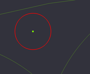
When you click the circle button, you click on the canvas where you want to place the center of the circle. You should be able to snap it to the center point we created above. Click again to set the diameter of the circle in the canvas. Once the circle is drawn, in the details pane to the left, verify the center is listed as (0,0,0), and the diameter is 111.
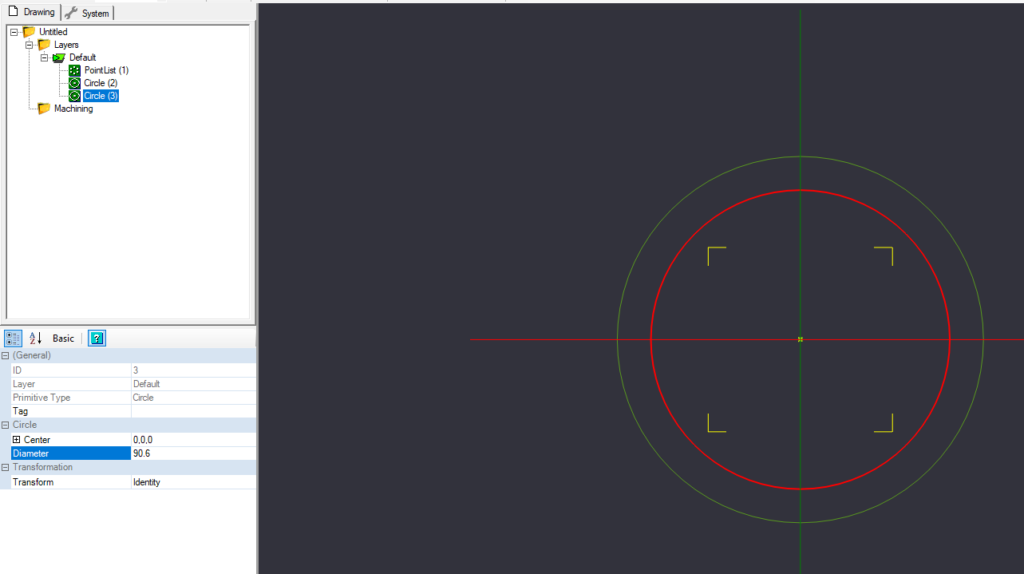
Create Circle, diameter 90.6mm – center at 0,0,0
We will create a 2nd circle for reference, similar to the previous circle, with the center at (0,0,0), but a diameter of 90.6mm.
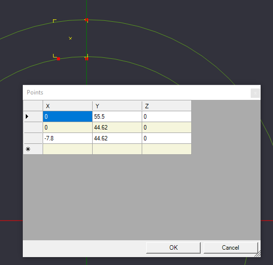
Create points at 0,55.5,0 & 0,44.62,0 & -7.8, 44.62,0
We will need to create 3 more reference points for the next step. Select Point List from the Toolbar, Draw Menu, or keyboard shortcut, and place 3 points in a backwards L shape near the top of outer circle, the top of the inner circle, and to the left of the previous point.
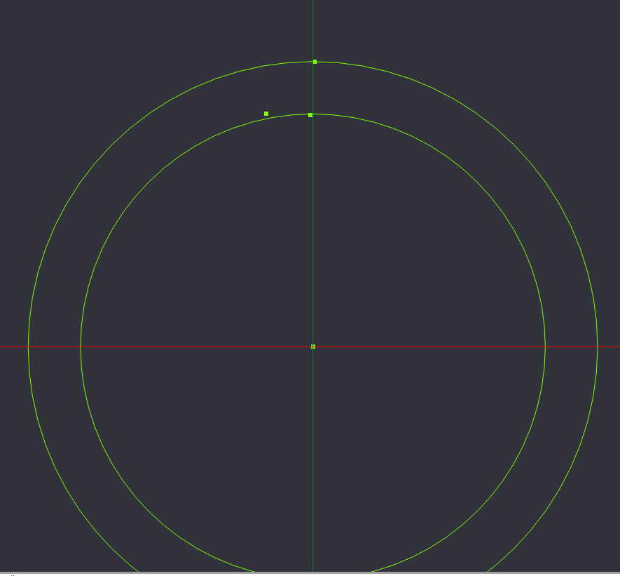
Press enter to confirm the 3 points, and go to the details pane to the left, and select the ellipsis to edit the point coordinates.
Set the 3 points to:
(0,55.5,0) [The top of the outer circle {Diameter of Outer Circle \ 2}]
(-7.8, 44.62,0) [Point on the inner circle, just to the left]
(0,44.62,0) [Point perpendicular to the previous point]
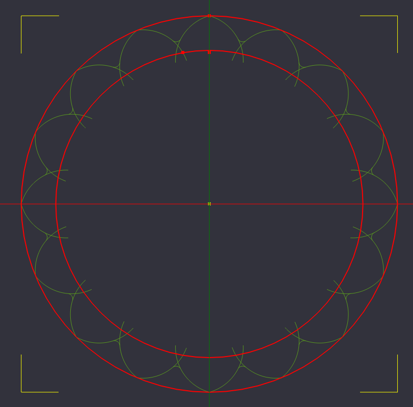
Create the Lobes of the Coin
Now we will use the points we just created to create an arc for our drawing.
Start by selecting Arc from the Toolbar or Drawing Menu.
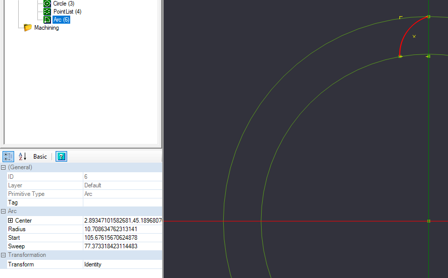
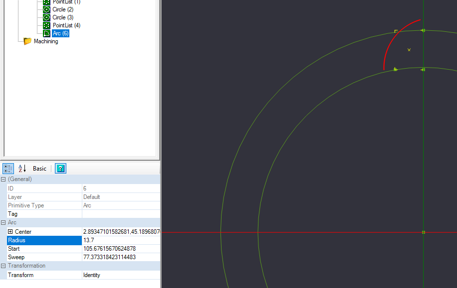
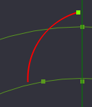
In the details pane of your arc, some of your data might not match what is in the reference image, and that is OK. Change the radius to be 13.7. After changing the number and pressing enter, the arc may move from its drawn position. We will correct that in the next step.
Now we will align the top of the arc with the top reference point we made.
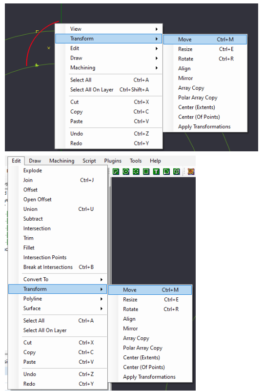
Select the Arc we created, and select from the Transform menu to move the arc. You can access Transform from the Right-Click Menu, or from the Edit->Transform Menu.
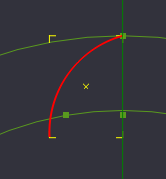
After you select the move command, you need to select the reference point to start the move from. Select the top of the arc.
From there, you are in a free move state. Click the point we created at the top of the outer circle to set the arc down at that location.
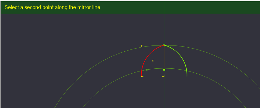
Mirror the Arc we just created and positioned
Now we will mirror the arc to create the final shape of one of our spokes.
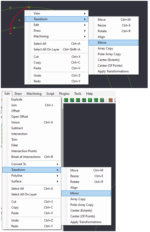
Select the arc we just placed and select Mirror from the Transform Menu, either by Right Clicking the canvas and selecting Transform->Mirror, or from the Edit Menu->Transform->Mirror
Once the Mirror command has been selected, we need to select our first reference point of where to mirror our part. Again, we will select the top point of our arc.
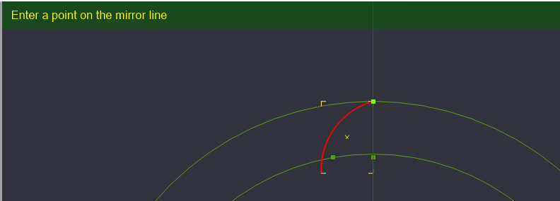
Now we will need to define the angle of our mirror’s reference line. Select the bottom reference point we created. You will notice a copy of the arc rotating around the upper reference point we selected. Once the angle point is reached, click to set the new object.
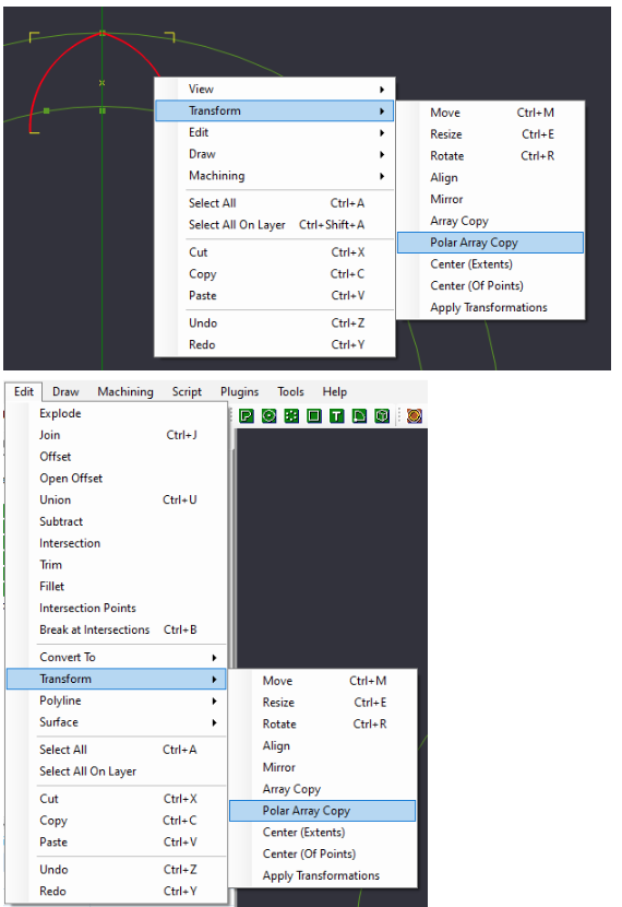
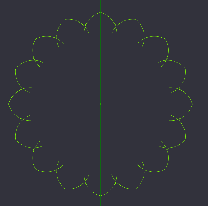
Use the Polar Array Copy option to duplicate these arcs
Instead of trying to recreate each of these arcs one by one, we will perform a copy of these arcs around a central point, a transformation called “Polar Array Copy”
Select the 2 arcs we created, and select Polar Array Copy from the Transform Menu, Right Click the canvas and select Transform->Polar Array Copy, or via Edit->Transform->Polar Array Copy
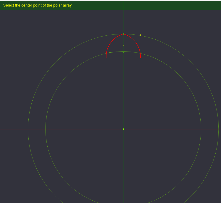
With Polar Array Copy Selected, it wants to know where the center point of the rotation will be located. Select the Center point at the origin we created.
With the center point selected, a dialog box will ask how many copies of the object you want to create. We want 16 lobes for our design, so we type 15 [one already exists].
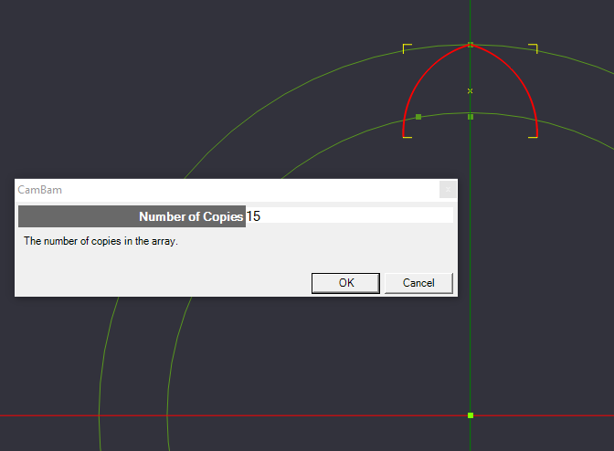
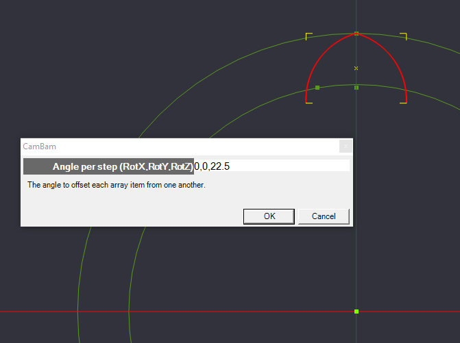
Click OK, and the dialog changes to ask how much to rotate the arcs and on what axis. We want to rotate the arcs around the Z axis by 22.5 degrees for each copy
[360 degrees / 16 total copies = 22.5 degree rotation]. Set the coordinates to 0,0,22.5 [X=0 degrees, Y=0 degrees, Z=22.5 degrees]
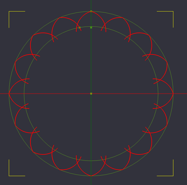
Click OK, and the copy is complete.
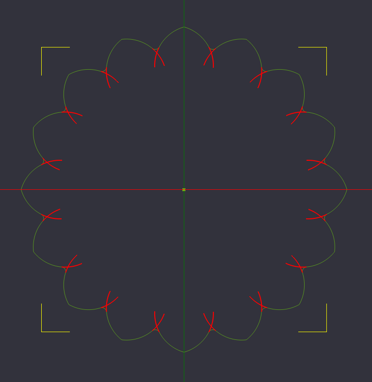
Smooth out the lobe transitions with tangent circles
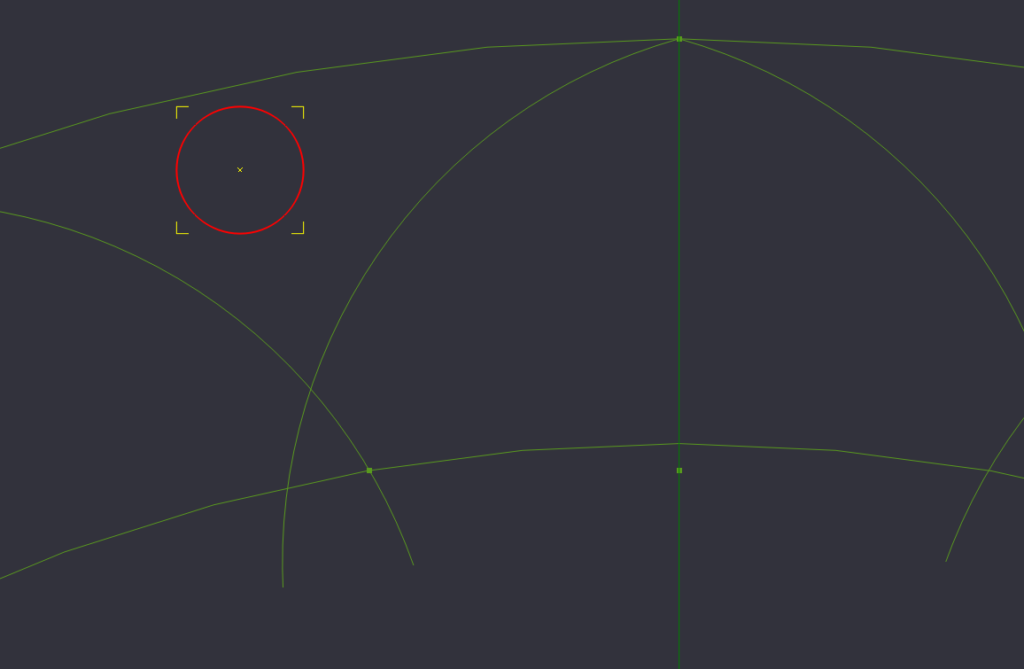
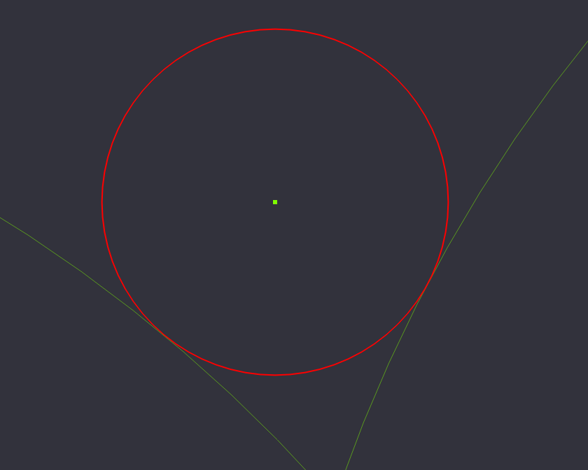
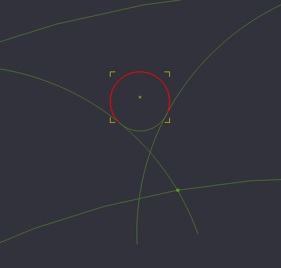
Next we will create a circle that we will use to fill in the areas between the lobes. To start, create a circle with a diameter of 3.2 in between the lobes.
Now we need to move the circle so that the edges of the circle just touch the the edges of 2 of the lobes.
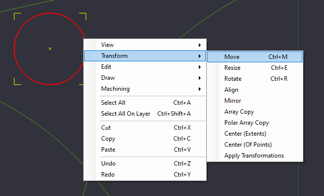
Select the Circle, and Select Move from the Transform Menu (Right Click->Transform->Move, or Edit->Transform->Move)
We need to select the reference point to start the move from, and in our case, it’s easy to select the center point of the small circle.
Move the circle so that it slightly overlaps 2 edges of the lobes. Positioning does not have to be perfect, but should be very close for the next operation.
Start cleaning up unused geometry
Now that we have the circle placed, we need to break the circle into pieces so that we are just left with the arc that will exist between the lobes.
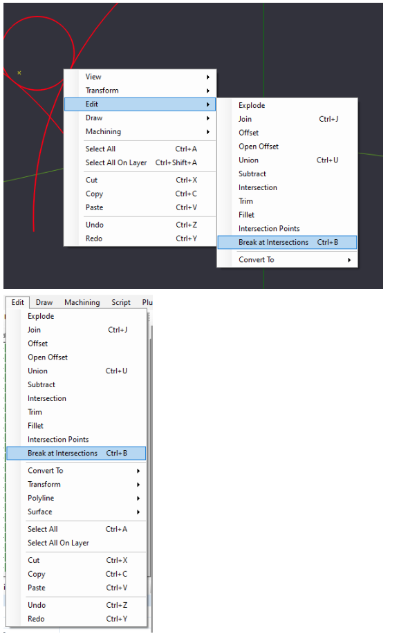
Hold the Control (CTRL) key on your keyboard, and select the circle, and the 2 lines of the lobe that the circle is adjacent to.
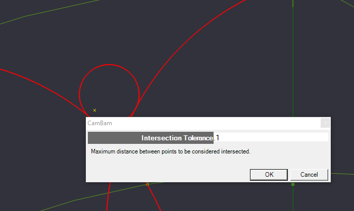
We will then select the option to “Break at Intersections” from the Edit menu. You can find this by Right Clicking on the canvas then Edit->Break at Intersections, or from the Edit Menu Bar->Break at Intersections
A dialog box will pop up and ask for the Intersection Tolerance. This is the Maximum distance that the lines can be apart, but still be considered intersected. For now, set it to .1. Increase this number and try again if the break command fails.
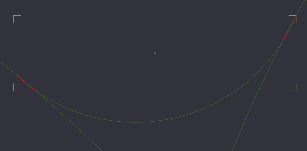
After the command completes, we should now be able to select only to top of the circle.
We can now delete the top of the circle, but the break command may have adjusted the geometry a little bit, so we need to zoom in to the intersection and delete any created overlap. Select the overlap (the arcing bits) and delete them, as well as the top of the circle.
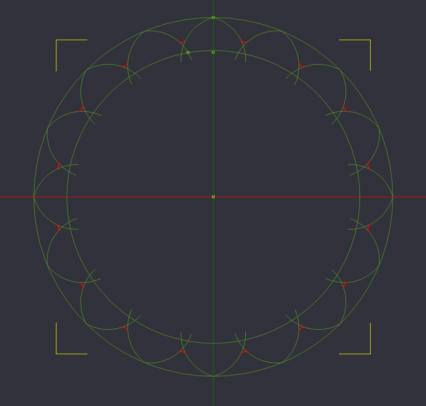
Again, we need this newly created arc to exist between all lobes, so we will again select the arc, and perform a Polar Array Copy to make 15 more copies at 22.5 degrees apart from the center of our design on the Z axis.
Cleanup Unused Reference Geometry
With our lobes now connected with an arc between them, we can now clean up some of our unneeded reference geometry. Select the outer circle, the inner circle, and the 3 points we created at the top of the circle and delete them.
We still have use for the center point, so leave that one alone for now.
With the reference geometry removed, we will have an easier time removing any extra overlapping lines
Break off internal lobe lines
Select all of the lines that we have created, and from the edit menu, Break at Intersections, with a tolerance of .1
This breaks the overlapping parts of the lobes with the arcs we made copies of, and allows us to trim away lines we no longer want.
Trim up more unused geometry
Select the now unneeded inner lines of the lobes, and delete them.
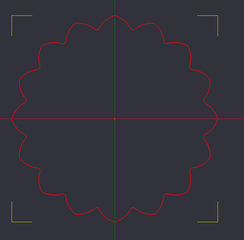
Join all lines into one cohesive object
Select all of the lines, and we will now join them together into a single workable object.
You can right click on the Canvas and select Edit->Join, or from the Edit Menu Bar->Join
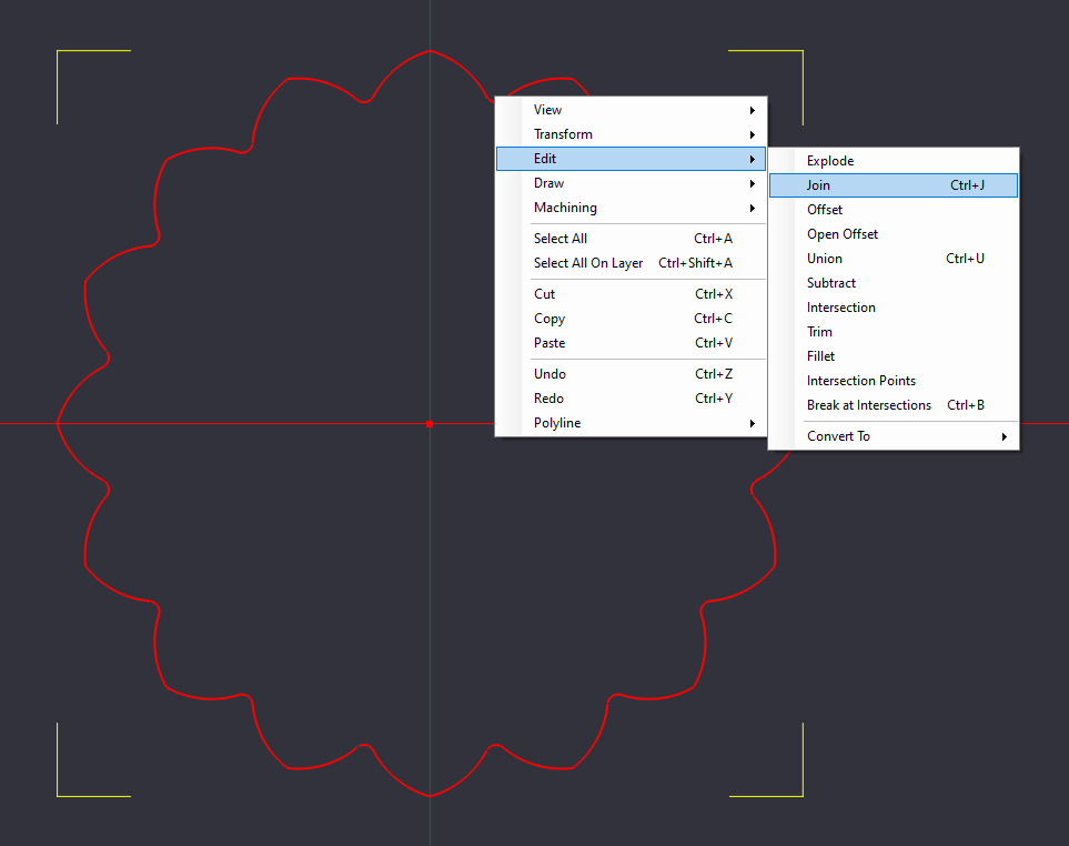
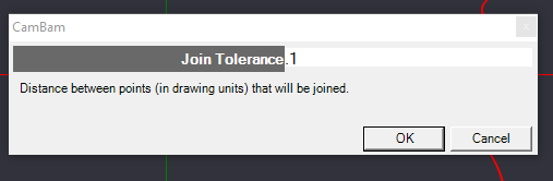
The Join Tolerance dialog box will pop up, and ask how far away the ends can be before the program will try to join them together. Again we can type “0.1”.
Increasing the tolerance will allow you to join lines that do not quite overlap or intersect.
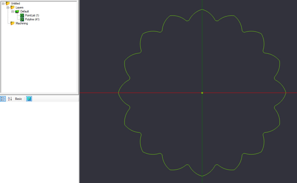
The two objects
With the lines now joined, we should only have 2 objects in the Object Pane to the left, a point list that when selected should highlight the center point of our design, and a PolyLine, which when selected should highlight all of the lobes and arcs we just joined.
Adding the Hackerspace PNP Logo
Next we will need to open a new instance of CamBam, to run alongside the one we are using now, so we can insert the Gainesville Hackerspace PNP logo. Find the CamBam plus shortcut in your application launcher (Start Menu on Windows, Applications Folder on Mac OS X)
When the new instance opens, we will need to open the Hackerspace PNP Logo DXF File.
This file can be downloaded at https://gainesvillehackerspace.org/static-content/HackerspacePNPLogo.dxf

Drag a select box around the logo, or use the Edit Menu->Select All.
Right click the logo and select Copy, or use the Edit Menu->Copy
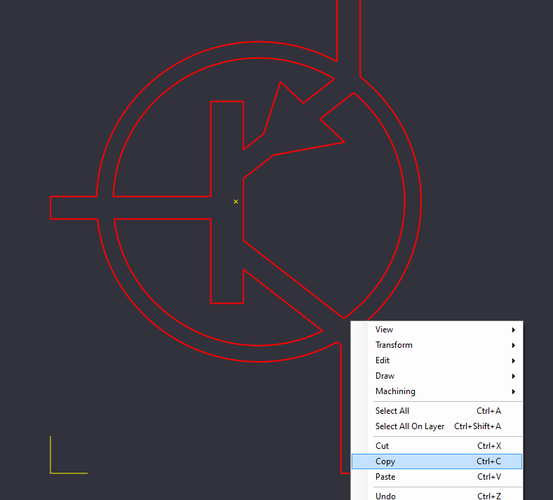
Switch back to the first instance of CamBam, and paste the copied logo, either by right clicking on the canvas and selecting Paste, or from the Edit Menu->Paste.
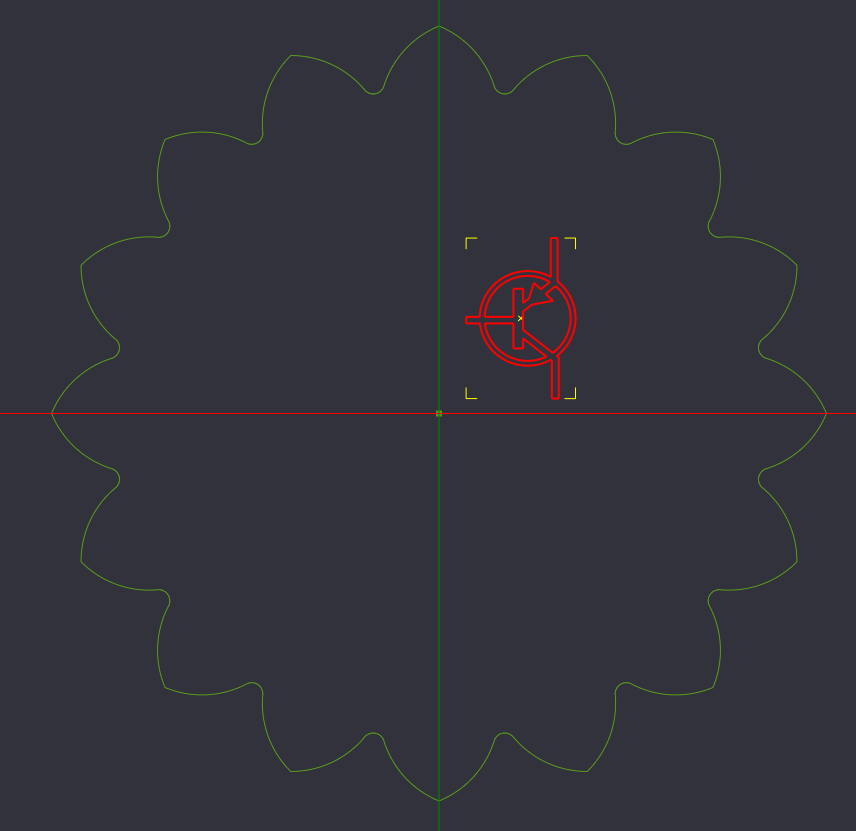
With the logo pasted, we need to resize it to that it works for our needs.
Right click the logo, and select Transform->Resize, or from the Edit Menu->Transform->Resize
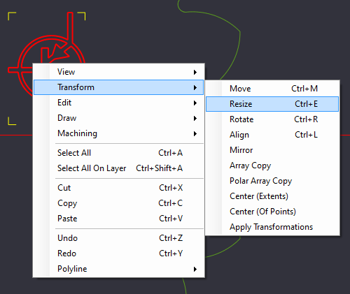
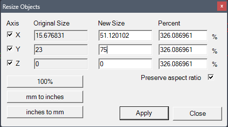
The Resize Objects dialog box will appear. Here you can select which axis to scale on, by size or percentage, and if you want to preserve the aspect ratio of what you are resizing.
Here, we want to scale all axes, with the aspect ratio preserved, and we want the PNP logo to be between 60 and 75mm tall.
With the PNP Logo resized, we now need to move it into place.
With the PNP Logo selected, right click the canvas and Select Transform->Move, or from the Edit Menu->Transform-Move
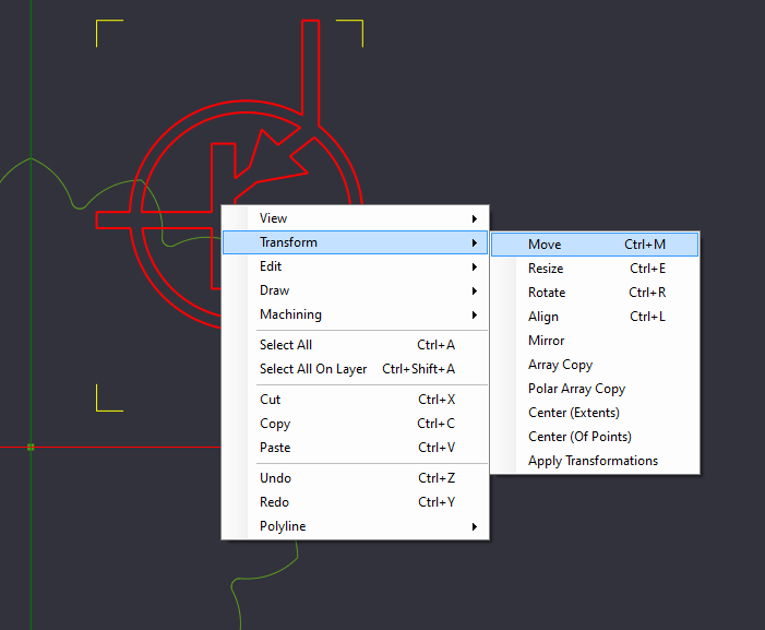
Select the Reference Point of where you want to start moving from, move the logo, and left click again to set the object in place.
Because the PNP Logo is not a uniform height and width, centering it may need to be done by eye.
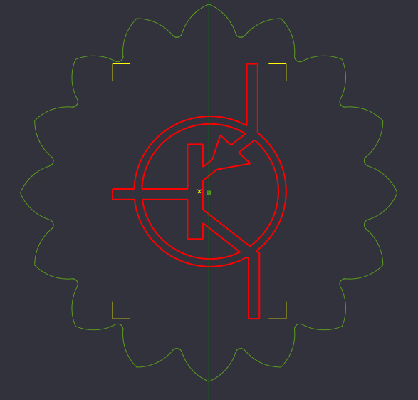
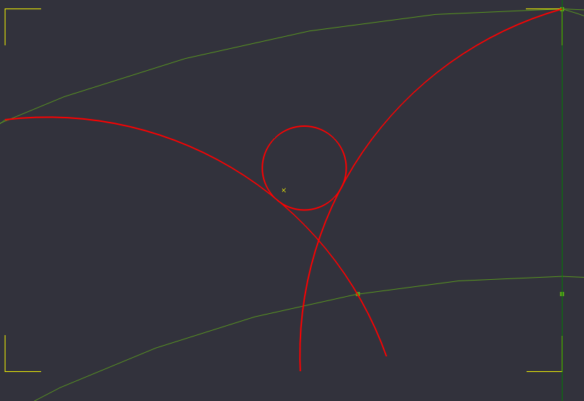
Finishing the Drawing
Draw a circle around the logo to enclose the geometry.
Select the Circle from the Drawing Toolbar, or from the Draw Menu->Circle.
Set the center point of the circle to the center of the workspace, and draw a circle. The size and positioning are not very important.
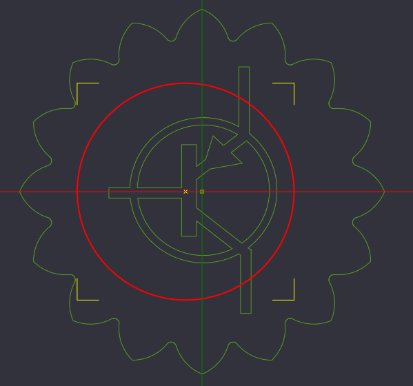
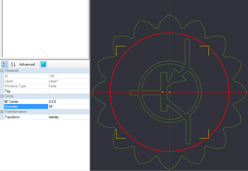
With the circle still selected, change the properties in the properties dialog menu in the bottom left.
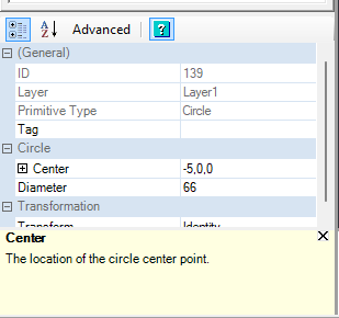
Set the Center Point to 0,0,0 [X=0, Y=0, Z=0]
Set the diameter to whatever you feel works best. This example is 85mm
Congrats!
You have completed the CAD portion of creating the Hackerspace MakerCoin!
The next steps are to decide how you want to make this coin a physical object:
Do you want to Laser Cut the MakerCoin?
Do you want to 3D Print the MakerCoin?
Do you want to CNC Cut the MakerCoin?
Do you want to make a Vinyl Sticker of the MakerCoin?