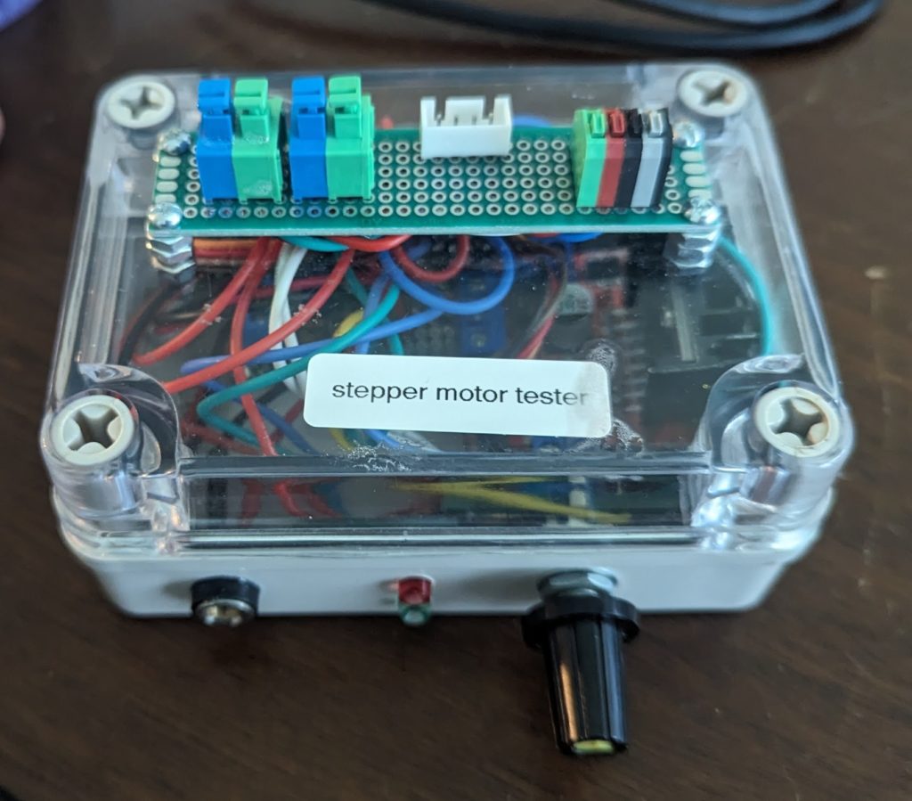
Stepper Motor Tester
Kamin Miller requested from one of our electronics minded members, Eric Pleace to see about making a simple stepper motor tester to test the large amount of NEMA 17 motors that we acquired as part of a large donation of 3D printer parts. The requirement was something that was easy to use, and stand-alone, as to not need an external control board for use.
What follows here is the usage of the Stepper Motor Tester, and the notes Eric took while making it.
Instructions for the Gainesville Hackerspace stepper motor tester.
(Initial Version, 5/3/2022; updated 7/14/2023; Eric Pleace)
A simple control unit to test 12V bipolar 2-phase 4-wire stepper motors. Most stepper motors are of this type.
Attach motor to be tested
The 3 sets of connectors on the top of the unit are wired in parallel. The left to contacts are for one of the stepper windings, the right 2 are for the other. Left and right pairs are interchangeable.
Attach power
This requires a barrel jack with 8-18V DC, center positive, reverse polarity protected. Current to the stepper is limited to less than 300mA or so and will draw no more than 350mA from the attached power supply.
The internal microprocessor (Arduino nano clone) requires a minimum supply voltage of around 6V, 20mA to start but the stepper motor controller needs about 8V minimum to operate correctly. Note that some motors will not start if the supply voltage is too low. Some broken motors will not start no matter what the supply voltage
Best to use about 12V.
Normal Operation
As soon a power on, the green LED will flash ½ sec on, ½ sec off.
This is the base line state and can be returned to anytime by pressing the encoder knob once or twice.
From the base state, pressing the encoder knob once will put the unit in manual test state. In this state power the green LED is on solid and the red LED flashes slowly (toggle between on and off every ½ sec).
Power is sent to any attached motor depending on the encoder rotation. Initially in this state the motor is off. Turning the encoder clockwise (CW) will run the motor one direction at a speed dependent on the rotary encoder – turning more in that direction increases speed, turning counter clockwise (CCW) will reduce speed, and turning CCW past the initial position will run the motor in the reverse direction.
Pressing the knob once will return the unit to the base state with the motor stopped, with the red LED off and the green LED flashing slowly.
From the base state, pressing the knob twice in about 0.6 seconds will set the unit it semi-automatic state with the green LED on and the red LED flashing twice per second.
In this state the motor is initially off. Turning the encoder CW by a click with cause the motor to continually rotate one direction then the other. More clicks in the CW direction cause the angle of rotation and the speed to increase. Turning in the CCW direction will slow the speed and reduce the rotation angle.
Pressing the knob with switch the unit back to base state.
General Notes
The rotary encoder used is not very consistent: sometimes presses will be missed and need repeating, sometimes rotation by single “clicks” will get missed and require repeating to be noticed by the unit.
No matter what the setting, the tester limits the current to any connected motor to less than 300mA.
The maximum speed of the motor is limited by setting a minimum of 1ms between the end of power to one set of motor windings to the start of power to the next set of windings. As a result, the maximum speed of motors may be faster than this tester can run.
The tester is intended for intermittent use. Using it continuously for long periods of time might result in the unit overheating and shutting down.
Design Notes:
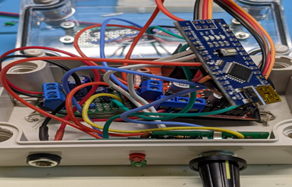
Overall Wiring View: A rats nest
Visible are:
The Arduino Nano, rotary encoder, indicator LEDs, power supply barrel jack, H-bridge controller board, power conditioner board.
Top of the box – connect the stepper motor to be tested here

Underside of the top board
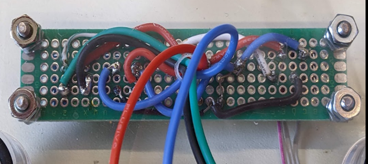
Rotary encoder board, caps visible, resistors on reverse.

LED board with 1k resistors, and end of encoder board with caps showing.
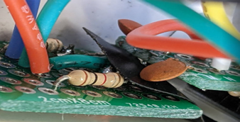
Front of the power conditioning board
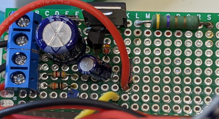
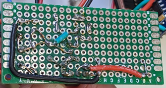
Reverse of power conditioning board
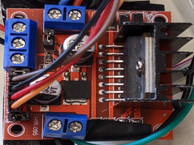
Dual H-bridge controller module: L298N
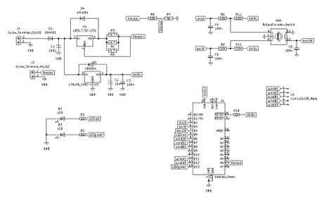
This diagram shows the polarity protected power conditioner circuit, the encoder debounce hardware, the red and green LEDs, and the Arduino Nano. It is close to what was built.

Updated: 4/23/2022 Saturday.
I’m not happy with the various stepper libraries – the ones I’ve tried offer good support for step-to-location but not so much for the continuous rotation I need for testing.
I’ll try writing my own functions.
Updated: 4/5/2022 6pm
Requirements:
- Small, light, quick, simple.
- Power from 12V, barrel jack, wall wart, regulated down for MCU (Arduino nano).
- Oled/lcd display (optional, preferred), LED indicators.
- Rotary encoder for input.
- Tests: short, open, crosstalk on windings; forward and reverse, slow, fast.
- Tests: current draw reasonable.
- For 4-wire motors.
- Overload protected.
- Direction, speed controlled by rotary encoder.
Controlled by Arduino nano: has >4 pins for analog read, >4 PWM pins, additional digital pins, 2 interrupt pins for rotary encoder, I2C for OLED display.
Operation:
Phase 1: check stepper motor windings for open, crosstalk.
Connect the 4 motor wires through 100ohm resistors to analog i/o pins on the MCU, and test with one pin in turn HIGH and read voltages at the other pins. Simply needs to be reasonable, not a highly precise test.
Phase 2:
Use the motor controller to run the motor forward or backward at variable speed based on the rotary encoder.
Components:
Possible H-bridge drivers on hand:
L9110 board (2 ICs): 2x motor windings, 0.8A, 2.5-12V, needs 4 pwm to control speed/direction
L298N board (1 IC): 2x motor windings, 2A, 5-35V, needs 4 logic plus 2 pwm to control speed
DRV8833 board (1 IC): 2x motor windings, 1.5A, 2.7-10.8V, needs 4 pwm to control speed/direction
L298N offers most headroom for current and voltage, and I have a board that had a bad diode replaced.
This table keeps track of Arduino nano pin used, USB connector at the top. (~=PWM, INT=interrupt possible),
it is speculation now but I’ll keep it updated.
| (has internal LED attached) | D13 | USB | D12 | Winding logic A1 |
| 3V3 | D11 | Winding logic A2 | ||
| AREF | ~D10 | |||
| Encoder switch | A0-D14 | ~D9 | ||
| LED green | A1-D15 | D8 | Winding logic B1 | |
| A2-D16 | D7 | Winding logic B2 | ||
| A3-D17 | ~D6 | both speed control PWM | ||
| A4-D18-SDA | ~D5 | LED red | ||
| A5-D19-SCL | D4 | |||
| Voltage sense | A6-D20 | ~D3-INT | Encoder input | |
| A7-D21 | D2-INT | Encoder input | ||
| 5V | GND | |||
| Rst | RST | |||
| GND | RX0 | |||
| VIN | TX1 |
For the proposed phases 1 and 2, the motor windings would need to be connected to the analog input and the H-bridge output at the same time, or isolate them with 4-pole switches. This leads to more complex circuitry than I’m comfortable with for this project, so Phase 1 is out as unnecessarily complex.
Proposed simplification
So the project reduces to current limited 12V input to motor controller, linear regulator for 5V for Arduino nano, rotary encoder with debounce, red led for errors, green for power.
Way easier.

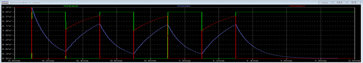
Rotary encoder with h/w debounce
Debounce circuit from Bourns (they make rotary encoders)
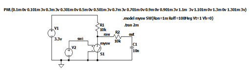
LTspice test below shows better bounce suppression with 100nF cap instead
of the 10nF used in the figure 2 to the right.

Using 10nF capacitor
Using 100nF capacitor
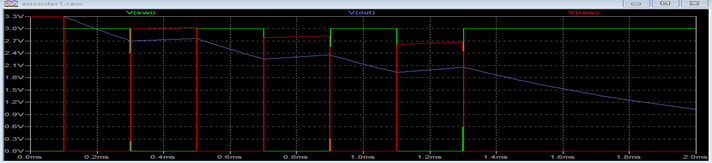
Notice in the lower picture the blue trace has less bounce.
Below is a schematic from Kicad. Barrel input jack, L298N motor controller are external.
Link to the Arduino Code: https://gainesvillehackerspace.org/static-content/wiki/Electronics/stepperTest3.ino
Link to the Kicad Design: <TBD>